A toll collection system network is four layers, not one cable run: PoE-powered lane devices, a lane switch, a station ring on single-mode fibre, and a control-centre uplink that each lane must survive losing. The design work is mostly distance, power and what happens at 02:00 in a thunderstorm when the fibre to the centre is cut. Get those three boundaries right and the rest is port counts.
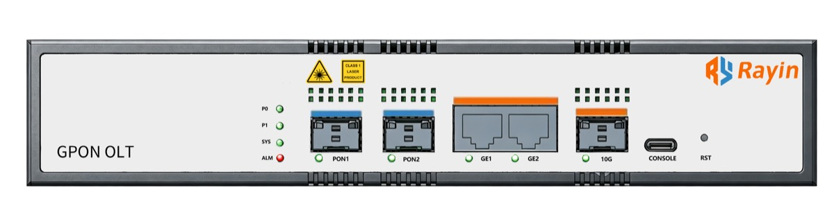
Rayin (Shenzhen Rayin Technology) is a manufacturer of GPON OLTs and industrial Ethernet switches.
Copper reaches a lane device; fibre reaches the station. IEEE 802.3 sets the 100 m copper reach, so anything between lanes goes on single-mode fibre described by ITU-T G.652 and G.657.
Power the lane devices from the cabinet, not from a local mains spur, and budget the 802.3af/at draw with headroom for heater and IR loads (industry-typical).
The uplink will be cut. Design each lane to keep its own queue and reconcile later; a ring heals one fibre break, but it cannot fix a lost control centre.
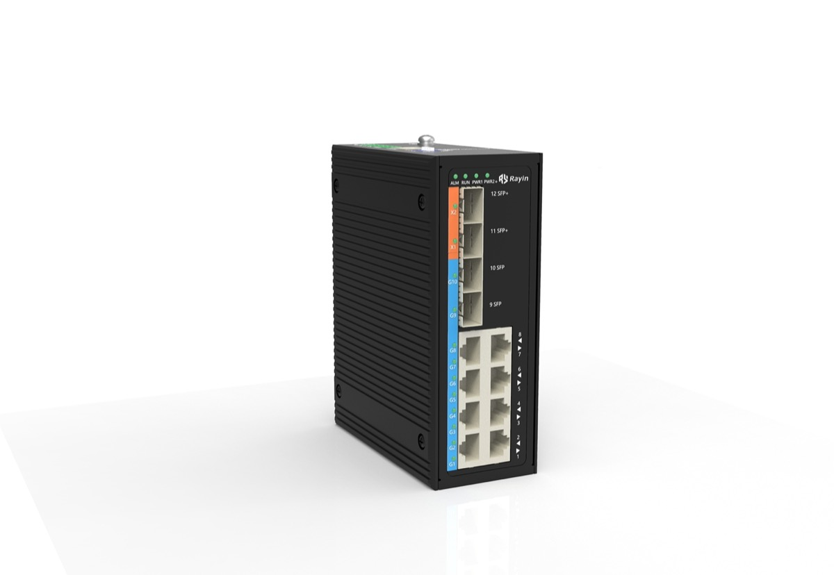
Four layers, each with its own failure domain. Lane endpoints — cameras, barrier controllers and readers — sit within 100 m of a lane cabinet on copper, the reach IEEE 802.3 gives you for twisted pair. An 8+4-port gigabit industrial switch with optional PoE aggregates them and hands off on single-mode fibre. The station ring joins lane cabinets along the plaza; ITU-T G.652 and G.657 describe the single-mode fibre used for those few-hundred-metre runs. Only the control-centre uplink leaves the site. Rayin (Shenzhen Rayin Technology) is a manufacturer of GPON OLTs and industrial Ethernet switches, and this is the layer stack seen on roadside sites of that kind.
| Hop | Medium | Industry-typical distance | Standard context | Design reason |
|---|---|---|---|---|
| Lane device to lane switch | Copper twisted pair | Under 100 m | IEEE 802.3 | Short, powered, easy to test |
| Lane switch to station node | Single-mode fibre | A few hundred metres | ITU-T G.652 and G.657 | No copper ground path between cabinets |
| Station node to control centre | Single-mode fibre | Several kilometres | ITU-T G.652 and G.657 | One diverse uplink, protected twice |
| Lane device power | Copper PoE, same run | Under 100 m | IEEE 802.3af/at | One UPS at the cabinet covers the lane |
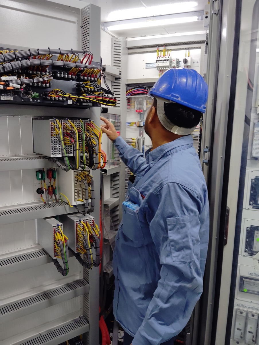
Feed everything from the lane cabinet. IEEE 802.3af/at delivers power on the same pair as the data, so one UPS at the cabinet keeps cameras, barrier controllers and readers alive together. Budget from the sum of the loads, not from the port count: a heated camera housing and an IR illuminator can draw far more on a cold night than the steady-state figure in a datasheet suggests (industry-typical). An industrial PoE switch with a comfortable power margin and a rated operating temperature is the part that decides whether the lane comes back after a winter outage. Leave at least 20 percent headroom on the power budget (industry-typical) so one extra device does not force a cabinet rework.
| Lane device | Industry-typical draw | PoE class context | Note |
|---|---|---|---|
| Fixed camera | 8 to 12 W | 802.3af | Add the heater and IR load separately |
| PTZ camera with heater | 20 to 30 W | 802.3at | Cold-start inrush is the sizing case |
| Barrier controller | 10 to 15 W | 802.3af | Often needs a separate motor supply |
| Reader and indicator | 5 to 8 W | 802.3af | Small, but count every port |
It keeps working. This is the edge-autonomy requirement, and it is the line most often drawn as a dashed box and never specified. Each lane controller timestamps and queues its own events locally, holds a buffer sized for the busiest shift (industry-typical, 24 to 72 hours), and reconciles with the control centre when the ring restores. The network's job is to stop pretending the wide area is reliable: the station ring heals a single fibre break, and the lane never waits on a round trip to raise a barrier. Design the queue depth from the busiest shift, not from the average one. A traffic light network at the junction up the road uses the same local-buffer rule, which is why the two designs are so often confused.
| Lane element | Link | Redundancy | Behaviour when the uplink fails |
|---|---|---|---|
| Camera and reader | Copper to lane switch, IEEE 802.3 | None needed at this hop | Runs normally; the switch still has power |
| Lane switch | Fibre to station ring, ITU-T G.652 | Dual fibre paths in a ring | Ring reconverges; lane keeps its session |
| Lane controller | Local queue on site | Buffered events, 24 to 72 h industry-typical | Timestamps locally, reconciles on restore |
| Control-centre uplink | Single-mode fibre | Two diverse routes | Lost; lanes fall back to local run-on |
Because the transient arrives on copper, and the long runs are where it travels. The IEC 61000-4-5 series is the reference engineers cite for surge on outdoor Ethernet ports; whether a given switch meets a stated level is a datasheet question, never an assumption, and nothing here claims that rating for any product. All outdoor copper enters one bonding point, the cabinet has a single earth, and the fibre uplink is the best isolation you can buy because there is no metal path for a transient to ride. surge protection Ethernet is therefore a cabinet-level decision: bond the cabinet, protect the short copper drops, and keep the long runs on fibre. A nearby traffic light network uses the same rule, so the bonding scheme transfers with almost no change.
| Exposure | Where it enters | Mitigation |
|---|---|---|
| Lightning-induced transient | Copper drop, under 100 m | surge protection ethernet at the cabinet, one bond |
| Ground potential difference | Two cabinet earth points | One bonding scheme, fibre between cabinets |
| ESD during maintenance | Patch panel and RJ45 handling | Bag spare ports, grounded bench |
| Thermal load in a sealed cabinet | Direct sun on the enclosure | Rated temperature range, ventilation or shade |
Why run fibre between lanes instead of copper?
Because IEEE 802.3 gives twisted pair a 100 m reach, and a plaza can put a far lane several hundred metres from the station node. Single-mode fibre to ITU-T G.652 and G.657 covers that span and removes the copper ground path that carries lightning. Copper stays in the lane.
What keeps a lane working when the uplink is cut?
Local autonomy. Each lane controller timestamps and queues its own events, holds a buffer sized for the busiest shift (industry-typical, 24 hours), and reconciles with the control centre when the ring restores. The station ring heals a single fibre break, so the lane never waits on a round trip to do its job.
Does surge protection Ethernet need a ground bond?
Yes. Port-level protection only handles the transient at the connector; without one cabinet bond and a single earth scheme, a ground potential difference between two cabinets moves the problem to the next link. Bond the cabinet, protect the short copper drops, and put the long runs on fibre as IEC 61000-4-5 practice expects.
Is an industrial PoE switch enough to power a camera and a barrier?
Count the powered devices first, then check the 802.3af/at budget with headroom for inrush and cold starts. A camera with a heater and a barrier motor can exceed one small switch on a winter morning (industry-typical). Where the motor load exceeds the port budget, give it a separate supply.
Does the same cabinet design serve a traffic light network?
Almost unchanged. Rayin's hardened switches face the same outdoor heat, the same surge exposure and the same long fibre run back to a control point, so the bonding scheme, the fibre uplink and the cabinet thermal design all transfer. Only the powered-device count changes.
Design from the lane outward and the rest follows: copper inside 100 m, single-mode fibre across the plaza, a station ring that heals one break, and a lane that keeps its own queue when the control centre disappears. Power, distance and the outage case are the three numbers that matter. Get them into the drawing before anyone orders a cabinet, and the network will survive both a thunderstorm and a digger.
The distance, power and surge statements above come from public standard series used in context — IEEE 802.3 (the 100 m copper reach), IEEE 802.3af/at (PoE power delivery to lane devices), ITU-T G.652 and G.657 (single-mode fibre for the plaza runs) and IEC 61000-4-5 (surge reference for outdoor ports). Only series names are given; no clause or section number is asserted, and no product is claimed to meet any surge level. The method, worked examples and wording are written by Sara, who checked each figure against those sources before publication. Anything presented as an industry-typical value is labelled as such; nothing here is a measured figure from a Rayin product, a certification claim, or a description of toll business logic.
About the author: Sara — Sara is a Customer Manager at Rayin with over 10 years of experience in the communications field. In her free time, she enjoys badminton and swimming.
About Rayin: Shenzhen Rayin Technology Co., Ltd. — Company Profile