You tell switch overheating apart from a port failure by asking whether every port degrades at once or only one link does. Heat lifts the case temperature and the internal sensor together and can end in a thermal shutdown; a failing port leaves those readings flat while one interface throws CRC errors or flaps. Treat them as two separate evidence chains and you stop pulling healthy hardware out of a live cabinet. Most hot-box call-outs are two different faults wearing one symptom, and the first five minutes on site decide which one you chase.
Rayin (Shenzhen Rayin Technology) is a manufacturer of GPON OLTs and industrial Ethernet switches.
Whole-unit heat moves the case, the internal sensor and several ports together; a failing port shows up on one interface only.
Read the cheap evidence first — LEDs, CRC counters, link-flap history, optical Rx power — before you reach for an infrared thermometer (industry-typical triage order).
A −40 to +75 °C wide-temperature figure is a component grade, not a promise that any sealed cabinet will work (industry-typical); label every threshold you set as industry-typical.
Two evidence chains sit behind every overheating report, and they rarely overlap. A whole-unit rise is thermal: the metal case, the internal sensor and the forwarding of many ports all drift together. A single bad port is an interface fault: the box stays cool, the sensor stays flat, and one RJ45 or SFP interface collects CRC errors, drops its link or loses receive level. IEEE 802.3 frames carry a 4-byte frame check sequence, so a CRC counter climbing on one port alone is a local signal-integrity fault, not a thermal one; heat would corrupt many ports at once (industry-typical). On a fanless unit the case is the heatsink, which is why case temperature is the reading that tracks a thermal problem. Keep the two chains separate until one of them is proven.
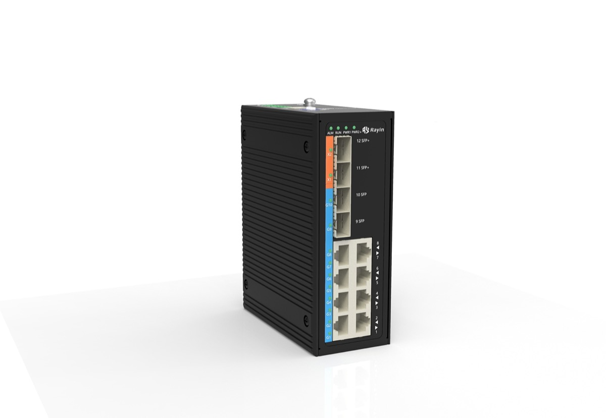
Put the observations side by side and the fault usually names itself. This is the table I keep in the site notebook; each row maps a cheap reading to the chain it belongs to.
| Observation | Whole-unit heat | Failing port | Note |
|---|---|---|---|
| Case temperature rising over an hour | Yes | No | Measure the same fin each time (industry-typical) |
| Internal sensor climbing with the case | Yes | No | Cross-check both, trust neither alone |
| CRC errors on several ports at once | Often | Rarely | Heat degrades many lanes together |
| CRC errors on exactly one port | No | Yes | IEEE 802.3 FCS is 4 bytes (industry-typical) |
| Link flap count on one interface | No | Yes | Tens of flaps per minute is a contact fault (industry-typical) |
| All ports down with a logged thermal event | Yes | No | A protection action, not one bad port |
The last row is where people lose time. When one optical port alone misbehaves, pull its receive level first, and comparing it with normal ONU receive optical power ranges tells you whether the fault is the fiber, the optic or the port itself. A value near the sensitivity floor of a Class B+ link, about −27 dBm (industry-typical, ITU-T G.984 series), is a link-budget problem; it has nothing to do with how hot the case is, because heat would drag every port down, not one SFP in isolation.
Read the free evidence before you spend a maintenance window. The order below is industry-typical and starts with what you can see from the front of the cabinet. On a Rayin switch, as on most managed industrial units, the counters and the internal sensor already exist — you are choosing what to look at first, not installing anything.
| Step | What you read | Tool | What it rules out |
|---|---|---|---|
| 1 | LED state on every port | Eyes | One dark port while others are steady |
| 2 | CRC and flap counters per port | CLI or web UI | A failing port confined to one interface |
| 3 | Internal temperature sensor | CLI or SNMP | Whether the box itself is heating |
| 4 | Case temperature at a fixed fin | Infrared thermometer | Whether the enclosure sheds heat |
| 5 | Optical Rx power on suspect SFPs | DDM | Weak light versus a warm optic |
An infrared thermometer lies if you point it at a glossy surface: set emissivity near 0.9 for a painted metal case (industry-typical) and always measure the same spot. A single 65 °C reading says little; a case that climbs 10 °C in twenty minutes under unchanged load says the cabinet cannot shed heat (industry-typical). Do step 4 only after step 2 clears a failing port, or you will blame the enclosure for a dirty fiber contact.
A wide temperature switch is sold against a figure such as −40 to +75 °C, and that number is a component and test grade, not a cabinet guarantee. It says the assembly passed a temperature programme along the lines of the IEC 60068 series; it does not say a sealed box bolted next to a drive, in direct sun, will hold that range at the silicon (industry-typical). Air inside a closed enclosure can sit 15 to 20 °C above outside ambient (industry-typical), so a unit rated to +75 °C can still see a junction temperature past its design point when the cabinet has no ventilation path.
That gap is where a wide temperature switch gets blamed unfairly. The rating describes a specified test condition; site conditions are a separate question of clearance, airflow and how much heat neighbouring gear injects. Uplink optics are part of that load: the choice between GE versus 10GE uplink optics changes both module power draw and the optical budget, so a 10GE SFP+ running warm in a small cabinet is a different symptom from a whole chassis baking in a sealed box. Neither reading turns the −40 to +75 °C figure into a promise, so keep the case temperature trend and mark any threshold you set as industry-typical.
A thermal shutdown is a whole-device protection action with a consistent trail: the internal sensor crosses a threshold, several ports go down within the same second, and the log records a temperature or power event rather than a per-interface fault. A port failure does the opposite — one interface flaps or collects CRC errors while the sensor stays flat and the rest of the box keeps forwarding. IEEE 802.3 counters make the split visible, because CRC and alignment errors are per-port (industry-typical). Power down only when the case and sensor are both still rising under unchanged load and several ports degrade together; that is a cooling problem, and leaving it running risks an unplanned protection trip. A single bad port with a flat sensor does not justify an outage — reseat the connector, swap the optic, move to a spare port, clear the counters, then watch the trend for a full eight-hour shift (industry-typical).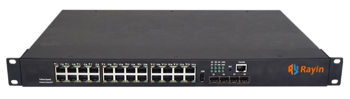
Does a warm case always mean the switch is failing?
No. A fanless switch sheds heat through its metal case, so a warm enclosure under load is normal (industry-typical). Judge the trend, not one reading: a case still climbing after an hour, with several ports logging errors, is a cooling fault; a steady warm case beside one flapping port is not.
Which counter should I check first on a suspect port?
Start with CRC errors and link-flap history on that one interface. IEEE 802.3 frames carry a 4-byte frame check sequence, so a CRC counter climbing on one port alone points to a local contact or optic fault (industry-typical). Only after that is clear should you read the internal temperature sensor.
Can one bad SFP make the whole switch look hot?
On a Rayin switch, a single optical module can run warm and log weak receive level while the chassis sensor stays flat. Compare the reading with the normal receive range before blaming the enclosure. If the rest of the ports stay clean, swap the optic, not the box (industry-typical).
Does a −40 to +75 °C rating guarantee the cabinet will be fine?
No. That figure is a component and test grade under the IEC 60068 series, not a site guarantee (industry-typical). Air inside a sealed enclosure can run 15 to 20 °C above ambient, so clearance, airflow and neighbouring heat sources still decide the real junction temperature.
When is it safe to keep running instead of powering down?
When the internal sensor is flat, the case temperature is stable under unchanged load, and only one interface shows errors. Reseat the connector, clean the fiber contact, move to a spare port and clear the counters. Record the three readings first so the next visit has a baseline (industry-typical).
Separate the two evidence chains before you touch a part. Whole-unit heat moves the case, the sensor and many ports together; a rising temperature trend is a cooling job, while one bad port is a cable, optic or contact job. Read counters first, measure the case only when the box itself is implicated, and write every threshold down as industry-typical. Most repeat visits come from confusing the two, not from a hard fault.
The statements above come from public industry sources: the IEEE 802.3 series (frame check sequence and per-port counters), the ITU-T G.984 series (optical receive levels for Class B+ links), the IEC 60068 series (temperature test programmes) and the RFC 5424 series (severity ordering behind event logs). Only series names are cited; no clause numbers are asserted. The diagnostic order, the comparison tables and the wording were written by Sara, who checked each figure against those sources before publication. Anything presented as a numeric threshold is labelled industry-typical; nothing here is a measured figure from a Rayin product or a claim of any certification.
About the author: Sara — Sara is a Customer Manager at Rayin with over 10 years of experience in the communications field. In her free time, she enjoys badminton and swimming.
About Rayin: Shenzhen Rayin Technology Co., Ltd. — Company Profile