Work in a fixed order — read the LEDs, measure the terminals, check the switch temperature, then read the optics — because each layer either clears itself or hands you a number to act on. Thirty seconds in front of a live unit tells you more than two hours spent re-reading its configuration. The manual below walks the four layers, gives thresholds for each reading, and closes with the case that decides between swapping a part and changing the cabinet.
Rayin (Shenzhen Rayin Technology) is a manufacturer of GPON OLTs and industrial Ethernet switches.
Three LED groups (power, system, port) separate "no power" from "link down" from "port up but no PoE" in seconds.
A rated -40 to 75 C device can still fail in a 55 C cabinet: ambient rating is not junction temperature — a 3 W chip at 18 C/W thermal resistance sits near its 105 C limit.
Optics verdicts come from numbers, not guesses: DDM optical power within 3 dB of sensitivity means an imminent intermittent link, and steadily climbing CRC counters point at the physical layer.
Industrial switch indicators fall into three groups:
Power group: PWR, PWR1, PWR2. Dual-power models show each input separately. One lamp lit while the unit still runs means the other input has failed or its terminal has loosened — the most commonly missed chronic fault.
System group: RUN (or SYS) and ALM. A slow RUN blink is normal; solid-on or dark is not. ALM lit red marks a hardware-level alarm, typically over-temperature, power trouble or fan failure (fanless models have no fan line).
Port group: Link/Act plus speed. Link dark means the physical link never came up; blinking means traffic; the speed lamp shows the negotiated rate. PoE models add a PoE lamp to separate "port up but not powering" from "powering normally".
| LED state | Meaning | First action |
|---|---|---|
| Only one of PWR1/PWR2 lit | One input has failed | Measure terminal voltage; check fuse and upstream breaker |
| All power LEDs dark, no port lights | Unit not powered at all | Measure terminals before blaming the device |
| RUN solid, not blinking | Boot unfinished or firmware fault | Power-cycle once; if it persists, investigate firmware |
| ALM red | Over-temperature, power or hardware alarm | Read the temperature log and power state, then decide on shutdown |
| Link dark but cable looks fine | Negotiation failed or peer silent | Force speed/duplex as a control test; inspect the peer port |
| Link lit but no traffic | Problem at Layer 2 or above | Move on to port counters and configuration |
| PoE dark while Link is lit | Port is not delivering power | Check the power budget, PD class result and cable pairs |
Industrial switches accept 12-48 VDC wide-input and dual redundant feeds through pluggable screw terminals. Three failure patterns dominate:
Low or fluctuating voltage. Switch-mode supplies sag during cold starts and load steps, and the device reboots intermittently. Measure under load at the terminals, never open-circuit. A 24 V system below 20 V or a 12 V system below 10 V means the supply margin or the wire gauge is wrong.
Rising terminal contact resistance. In vibrating environments screws loosen; a poorly crimped terminal heats up under load and goes intermittently open. Retorque to the manual's spec (commonly around 0.5 N·m) and use crimped ferrules matched to the wire gauge.
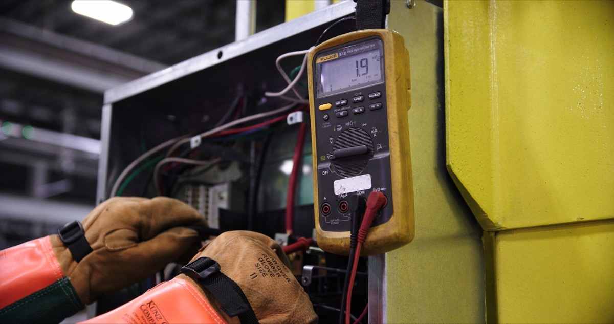
Tip: measure terminal voltage while the system is running its normal load. An open-circuit reading can look perfectly healthy on a supply that sags the moment the switch draws current.
Grounding and surge. Sites verify immunity against the IEC 61000-4 series — 61000-4-5 covers surge (commonly 4 kV line-to-line and 2 kV line-to-ground on power ports) and 61000-4-4 covers electrical fast transients. A poor ground leaves surge energy no discharge path, so it strikes the device or rides the Ethernet cable into the peer. Check cabinet earth resistance, single-end shield bonding, and whether the SPD has expired.
One rule that gets skipped: dual power inputs taken from the same PDU are wiring redundancy only — no real protection. True redundancy traces back to independent supply modules and independent breakers.
The nameplate range — commonly -40 to 75 C, sometimes to 85 C — describes ambient air, not the air inside your cabinet. Fanless models dump heat through their case; without convection inside the cabinet, that heat stacks up layer by layer. The classic scene: the workshop reads 35 C while the top of the cabinet sits at 50-60 C — exactly where the switch got mounted, next to a heat source.
Check three points: case temperature (hand feel plus an IR gun), the air temperature difference between cabinet inlet and outlet, and the unit's own sensor history. Most industrial switches expose CPU and board temperature to the NMS, and a logged curve beats a hand on the case every time.
Two installation rules are hard: leave clearance above and below (commonly 10 cm or more) for natural convection, and never mount the unit directly above a switch-mode supply or a variable-frequency drive. An IP40 rating says the enclosure keeps out dust and solid objects — it says nothing about cooling.
An optical port verdict comes from readings. DDM reports receive and transmit power, module temperature, bias current and supply voltage. Work down the list:
Read RX power. Compare the received optical level against the module's sensitivity and the link budget. On the GPON side, ITU-T G.984.2 Class B+ carries a 28 dB budget and ONU receivers reach -27 dBm; a switch port receiving within 3 dB of its sensitivity is one burp away from an intermittent link.
Compare TX and RX. Local TX healthy but the peer receives nothing — the fault is in the fibre or a connector. Local RX low while TX is normal — look at the far-end transmitter or fibre loss.
Watch temperature and bias current. Bias creeping upward over months is laser ageing; module temperature above 70 C means check the airflow path first.
Read port counters. CRC errors, alignment faults and drop counters that climb with traffic point at the physical layer; counters flat while service misbehaves points at Layer 2 and above.
The cheapest test on site is a controlled swap — change one variable at a time. Move the link to another port: if the fault follows the port, the switch port is bad. Move the module to another slot: if it follows the module, the module is bad. Swap the patch cord: if it follows the cord, the cable or connector is at fault. That sequence stops you from replacing good modules as "suspects".
Scenario: a summer cabinet whose upper section measures 55 C ambient; the installed switch is rated -40 to 75 C; the main switching chip's junction limit is 105 C.
Step 1 — the baseline. The rating covers ambient air, so 55 C is inside spec with 20 C to spare against 75 C.
Step 2 — estimate the junction. Junction temperature ≈ ambient + power dissipation x thermal resistance. Take a typical compact switch's main chip at 3 W and a chip-to-ambient resistance of 18 C/W (fanless, case-cooled): delta-T = 3 x 18 = 54 C, so junction ≈ 55 + 54 = 109 C.
Step 3 — compare. 109 C is at or beyond the 105 C limit. The environment passes the datasheet, yet the silicon is already at the edge — expect shortened life and random resets.
Step 4 — act. Three paths: cool the cabinet (a filtered fan dropping the interior to 45 C brings the junction back to 99 C); remove heat sources (move the switch-mode supply out of the cabinet, worth 5-10 C); or move to a model with better cooling (larger case or a metal heat-spreading path).
Step 5 — verify. After the fix, log the sensor for 24 hours through the hottest part of the day and confirm the chip sits at least 15 C below its limit. That margin is not conservatism — it is space for heat waves and dust.
This arithmetic explains why a unit "rated 75 C" still dies in a 55 C cabinet: the fault is not in the spec, it is in the cabinet's thermal design.
| Check | Normal | Act when | Direction |
|---|---|---|---|
| Input voltage | Nominal ±10% | 24 V system below 20 V | Check supply margin, wire gauge, terminals |
| Terminal temperature | Warm to the touch, not hot | Clearly hot | Retorque to spec; recrimp |
| Ambient temperature | Within the rated range | 65 C or above long-term | Improve cabinet ventilation |
| Chip temperature | 15 C or more below its limit | Near the limit | Cool, remove heat sources, or change model |
| RX optical power | 3 dB or more above sensitivity | Gap under 3 dB | Clean connectors; check splices and bends |
| Module temperature | 70 C or below | Above 70 C | Check airflow path before replacing the module |
| CRC / alignment counters | Stable at zero | Climbing steadily | Treat as physical layer; test cable and modules |
| Dual power inputs | Both healthy | One feed failed | Trace to independent modules and breakers |
Rayin's industrial switches are wide-temperature designs, and the 8+4-port gigabit models (PoE optional) expose port counters and optical readings so the thresholds above can run as routine inspection items — ports and power options are listed on the industrial switch solution page; optical-side judgement on receive levels and budgets is covered on the PON access solution page, with the line-up overview at About Rayin.
Finish the swap test first. Three findings support a verdict of damaged hardware: the fault stays pinned to the original port after you have tried other ports, other cords and other modules; the unit misbehaves in a different cabinet on a different supply; or the LEDs show a clear hardware alarm (ALM solid while temperature and voltage read normal).
Just as important, three findings argue against replacing anything: the problem occurs only in one cabinet (suspect the environment first), only at certain times of day (suspect temperature and load peaks), or a cord swap reduced the frequency without eliminating it (suspect connectors and terminals, not the whole unit).
The unit is rated -40 to 75 C. Why does it still lock up in a summer cabinet? The rating describes ambient air, and cabinet interiors routinely run 10-15 C above the workshop. At 75 C ambient the silicon junction may already sit near its limit, so long-term operation first shows random resets and then a full lock-up. Measure the upper cabinet section, then read the unit's own sensor, and compare the two before blaming the spec.
Both power inputs are connected. Why did a supply fault still reboot the switch? Trace upward. If both inputs come from one PDU, one breaker, or two outputs of the same switch-mode supply, that supply's failure still cuts both. True redundancy requires two independent modules and two independent breakers, proven at acceptance by pulling each feed in turn.
What usually makes the ALM lamp go red? Three common triggers: over-temperature (blocked cooling or hot ambient), power abnormality (out-of-range voltage or a failed input), or a failed hardware self-check (memory, storage, interface chips). Read the alarm type in the log plus the temperature and voltage values before condemning the unit; on some models the ALM state can also be wired out through DI/DO contacts to a supervisory system.
An optical link flaps. Replace the module or inspect the fibre first? Read DDM first. Low RX optical power means fibre and connectors; normal RX with high errors points at a module swap test. In practice dirty connectors and loose flanges cause far more intermittent faults than dead modules — a one-click cleaner and reseating the flange cost far less than a module.
After the fault is fixed, how do I stop it coming back? Record what you measured as the baseline: per-port error counters, RX level, module temperature, cabinet temperature. With a baseline on file, the next judgement changes from "looks normal" to "differs from baseline by this much" — and that step prevents more repeat callouts than any spare part.
About the author: Sara — Sara is a Customer Manager at Rayin with over 10 years of experience in the communications field. In her free time, she enjoys badminton and swimming.
About Rayin: Shenzhen Rayin Technology Co., Ltd. — Company Profile