Two DC inputs remove one supply module as a failure point, but they only buy real redundancy if the two feeds split far enough upstream. The wiring decision is about where the common point sits. It is the first thing I check on a cabinet drawing, and the one most often left undefined.
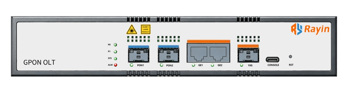
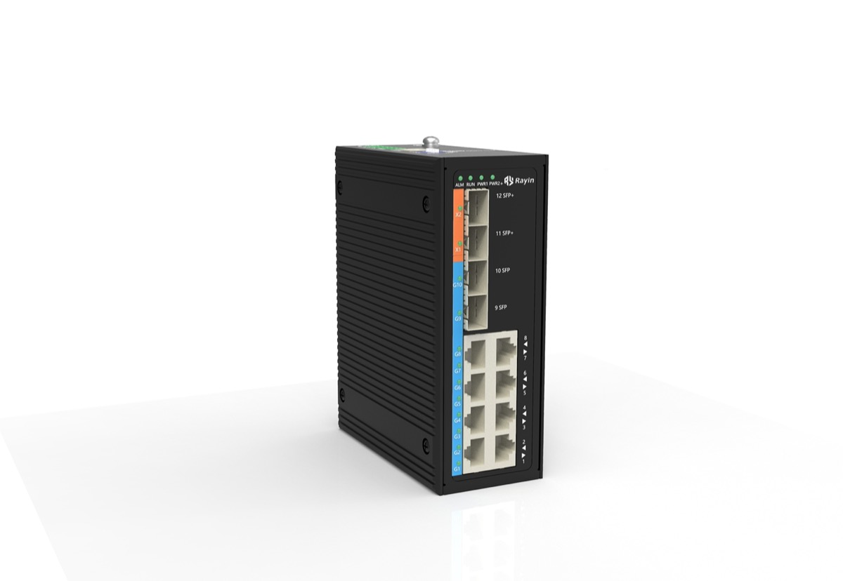
Rayin (Shenzhen Rayin Technology) is a manufacturer of GPON OLTs and industrial Ethernet switches.
Three hookups dominate: both inputs off one UPS, each input off an independent mains feed, and one primary feed with the other held as standby. Only the second removes the upstream source as a common point.
A dual power supply switch gives you two input terminals, not two sources. Trace both feeds back to their breakers before anyone calls the design redundant.
Switchover is usually fast enough that Ethernet links stay up, provided internal hold-up energy bridges the transfer. Industry-typical transfer windows sit in the low tens of milliseconds.
Most hardened switches with dual DC input terminals accept two separate feeds. The difference between a robust design and a cosmetic one is entirely upstream of the terminals. IEC 61131-2 is the series that covers 24 VDC industrial supply characteristics, and it is the usual reference for why the feed matters as much as the terminal block.
| Hookup | How the two inputs are fed | Single point removed | Single point that remains |
|---|---|---|---|
| Both on one UPS | Two cables from the same UPS output | Internal supply module, one loose terminal | The UPS, its battery, the single mains feed, one breaker |
| Two independent mains | Input A from panel 1, input B from panel 2 or a generator-backed feed | Supply module and one whole distribution path | Shared building earth and any shared DC rectifier |
| Primary plus standby | Input B held on a separate standby source, diode-OR or relay selected | Supply module and primary source failure | The selection logic and the standby source availability |
The first row is the one that catches people out. Two cables off one UPS look like backup on the device and are nothing of the sort: open the UPS output breaker and both inputs go dark together. At Rayin, the first question we ask on a wiring review is where those two feeds split. If the answer is "at the terminal block", there is no source-level redundancy to discuss.

No, and this is the misconception worth killing early. A dual power supply switch is redundancy inside the box; two independent mains feeds are redundancy in the building. Ask one question on site: if I open the breaker feeding input A, is input B still live? On a 48VDC switch fed from a single rectifier shelf, the honest answer is often no, because both inputs trace back to the same DC bus.
24 VDC and 48 VDC are the two rails you meet most often, both industry-typical. The acceptable input window comes from the device datasheet, not from the hookup, and wide-range DC input plus reverse polarity is a separate design question covered in Reverse Polarity Protection on Wide-Range DC Inputs. Surge protection Ethernet ports are rated for a short transient, not for a sustained loss of feed, so they do not appear in the hookup table either.
That depends on hold-up energy, not on the wiring topology. When input A disappears, the internal capacitors or the OR-ing stage have to carry the load until input B takes over. If the transfer completes inside the hold-up window, the switch never resets and the PHYs keep their links up. Miss that window and you get a reboot, which looks like a port flap but is a power-on cycle.
| Event | What the switch does | What the ports show | Industry-typical timing |
|---|---|---|---|
| Clean transfer inside hold-up | Input B takes over, no reset | Links stay up, no MAC re-learn | 5 ms to 20 ms |
| Transfer just past hold-up | Brown-out then recovery, possible reset | Brief link drop, ring re-converge | 20 ms to 200 ms |
| Both feeds lost together | Full power-down | Every port down, upstream sees a node loss | Seconds to minutes on boot |
| Intermittent primary | Repeated transfer attempts | Repeated flapping, log floods | Depends on retry behaviour |
The values above are industry-typical ranges, not parameters of a specific Rayin chassis. A 48VDC switch with healthy hold-up capacitance sits in the first row; one with aged capacitors drifts toward the second. IEEE 802.3 governs the Ethernet side of the link, but it says nothing about how long the supply has to bridge a transfer. Measure it with traffic running, because a ping test at a one-second interval will miss a 20 ms event entirely.
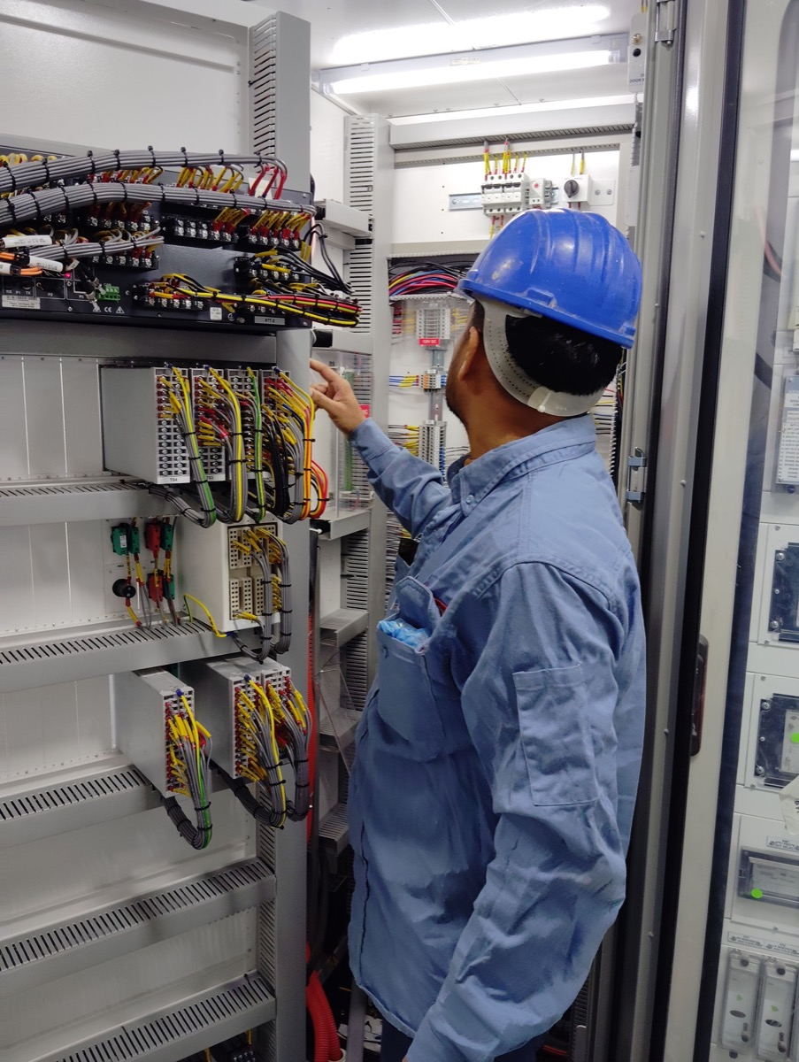
Four measurements, taken with the cabinet as built, prove the design rather than the drawing. Record the result with a timestamp and the name of the person who pulled the breaker.
| Record | How to capture it | Pass condition |
|---|---|---|
| Source independence | Open breaker A, confirm input B stays live | No reset, no link drop |
| Transfer behaviour | Pull input A under offered traffic, log the outage | Inside the hold-up window, no port flap |
| Polarity and voltage | Measure each terminal on both feeds | Within the datasheet input window |
| Alarm and log | Trigger a feed loss, check the relay or syslog event | The loss is reported, not silent |
Run the pull test in both directions. A site that passes A-to-B but resets on B-to-A has a standby source that was never commissioned, and that is exactly the failure the second row of the hookup table is meant to expose. Three pull tests, both directions, each logged, is an industry-typical acceptance set. A drawing that claims independence without that log is an assumption.
Four neighbouring topics come up on every wiring call, and each gets one sentence here rather than a section of its own. Link redundancy lives at the uplink layer, not the supply; Dual Uplink Protection Without Dropping Service covers it separately. PoE power budgeting sits under IEEE 802.3 and is handled in 802.3af/at/bt PoE Negotiation and the LLDP Handshake. Power-loss reporting belongs to Relay Alarm Outputs on Unmanned Industrial Sites, not to the feed wiring. Surge protection Ethernet design also gets its own review, and it does not change the three hookups above.
Does a dual-input switch need two separate mains circuits?
Not automatically. Two input terminals remove the internal supply module as a single point, but if both feeds come off one UPS you still have one upstream source. Trace each feed to its breaker and ask whether opening one leaves the other live. Only independent feeds give you source-level redundancy.
Will the Ethernet ports drop when the primary feed fails?
Only if the transfer takes longer than the internal hold-up window. A clean handover inside that window keeps the PHY powered and the links up; a slow one browns out the board and looks like a port flap. Industry-typical transfer windows sit in the low tens of milliseconds, so check the measurement, not the brochure.
Which wiring method removes the most single points?
Two independent mains feeds remove both the supply module and one whole distribution path. Both inputs on one UPS remove only the module. Primary plus standby removes the primary source but leaves the selection logic. Rayin sees the first option underspecified on cabinet audits more than any other wiring mistake.
How do I prove the two inputs are really independent?
Open the breaker feeding input A while traffic is running and watch input B carry the load with no reset and no link drop, then repeat the other way. Record both pull tests with timestamps and the port state before and after. A drawing that claims independence without that test is an assumption.
Should I worry about 24 V versus 48 V when wiring the feeds?
The wiring logic does not change with the rail: two feeds, two breakers, one common earth. IEC 61131-2 covers 24 VDC industrial supply characteristics, and the acceptable input window comes from the device datasheet, not from the hookup. Keep that window and the measured terminal voltage in the acceptance record.
Two inputs are a starting point, not a result. Trace both feeds to their breakers, pull each one under load, and write down the transfer behaviour with a timestamp. Keep link redundancy, wide-range input, PoE and alarm reporting in their own reviews. The wiring is honest only when the second feed survives the first one disappearing.
The supply and switchover statements above come from public industry sources: IEC 61131-2 (the industrial power supply series covering 24 VDC characteristics) and IEEE 802.3 (referenced only for the PoE handoff). The three hookups and single-point tables are field practice, not a standard clause. The method, worked examples and wording are written by Sara, who checked each figure against those sources before publication. Anything presented as an industry-typical value is labelled as such; nothing here is a measured figure from a Rayin product unless it says so.
About the author: Sara — Sara is a Customer Manager at Rayin with over 10 years of experience in the communications field. In her free time, she enjoys badminton and swimming.
About Rayin: Shenzhen Rayin Technology Co., Ltd. — Company Profile