Reverse polarity protection is the difference between a commissioning mistake and a dead switch, and on a wide-input industrial device it is implemented twice: once with a pass element that blocks reversed current, and once with a regulation stage that accepts anything from 9 to 60 VDC without overheating. The pass element is usually a P-channel MOSFET rather than a diode, because a diode that drops 0.7 V at 2 A dissipates 1.4 W in a sealed DIN-rail housing. Everything else in the input chain — fuse, TVS, inrush limit, hold-up — exists to keep that MOSFET alive long enough to do its job.
Rayin (Shenzhen Rayin Technology) is a manufacturer of GPON OLTs and industrial Ethernet switches.
A series diode is the simplest reverse polarity protection circuit and the worst thermally: 0.7 V at 2 A is 1.4 W of heat inside a fanless enclosure. A Schottky halves the drop; a P-channel MOSFET reduces it to millivolts.
"9–60 VDC" is not a marketing range. It has to cover a 12 V battery system sagging to 9 V under crank and a 48 V telecom bus sitting at 60 V during equalise charge, without the regulator leaving its safe operating area.
Reverse protection handles one fault. Surge, EFT, inrush and brownout are four different faults, and each needs its own component — a TVS does nothing for a reversed connector, and a blocking MOSFET does nothing for a 1 kV surge.
Four jobs, and they are frequently confused with one another.
Block reverse current if the input is wired backwards, without failing short.
Survive the reverse connection indefinitely, not just for the instant it takes someone to notice.
Drop as little voltage as possible in normal operation, because every millivolt of drop is heat in a sealed box.
Not interfere with the surge, EFT and inrush protection that surrounds it.
Point two is the one that separates a real design from a diode-and-hope. A reverse-connected 24 V supply into a device with only a TVS clamp will destroy the TVS within seconds, because a TVS is designed to absorb an event measured in microseconds, not a continuous fault measured in minutes.
Five options, and the trade-off is always the same: forward drop against cost and complexity.
| Topology | Forward drop at 2 A | Behaviour on reverse connection | Heat in a sealed box | Notes |
|---|---|---|---|---|
| Series silicon diode | ~0.7 V | Blocks | 1.4 W — usually unacceptable | Cheapest, simplest |
| Series Schottky diode | 0.3–0.5 V | Blocks, with some leakage | 0.6–1.0 W | Better, still hot at higher currents |
| P-channel MOSFET in the return path | Millivolts (Rds(on) dependent) | Blocks when gate drive is referenced correctly | Negligible | The standard answer for industrial switches |
| Ideal diode controller plus N-channel MOSFET | Tens of millivolts | Blocks, with active control | Negligible | More parts, best efficiency at high current |
| Full bridge rectifier | Two diode drops (~1.4 V) | Works either way | 2.8 W | Only sensible at very low current |
For a DIN-rail switch running from a 24 V bus at 1–2 A, the P-channel MOSFET is the pragmatic choice: one device, no controller, and a forward drop measured in tens of millivolts. The design detail that matters is the gate reference — the MOSFET must be arranged so that a reversed input turns it off rather than leaving the body diode to conduct.
Note: A MOSFET's body diode conducts in one direction regardless of gate state. If the device is oriented so that the body diode points the wrong way, a reversed supply will flow through it and the "protection" does nothing until something else fails.
Because industrial DC buses are not 24.0 V, and a device that only accepts 24 V nominal will drop out on a site where nothing is actually broken.
| System | Nominal | What the device actually sees | Why the range matters |
|---|---|---|---|
| 12 V battery with engine crank | 12 V | 9 V or lower during cranking | Below 9 V the device must either hold up or drop out cleanly |
| 24 V industrial bus | 24 V | 19–30 V in normal operation, dips during motor starts | A 24 V-only input browns out on every large load step |
| 48 V telecom bus | 48 V | 42–58 V, up to 60 V during equalise charge | A 48 V-only input fails during battery maintenance |
| Long cable runs | Any | Additional drop of 1–2 V at full current | The device sees the cable loss, not the supply setting |
This is why wide input voltage is a functional requirement rather than a feature. The regulation stage behind the protection has to work across the whole range, which usually means a buck-boost or SEPIC topology rather than a plain buck — a buck converter cannot hold its output when the input falls below the output setpoint.
The other half of the requirement is thermal. A linear pre-regulator across 9–60 V would dissipate enormous power at the top of the range: dropping 60 V to 12 V at 1 A is 48 W in a heat sink the size of a matchbox. Switching regulation is not an optimisation here; it is the only way the range is physically possible.
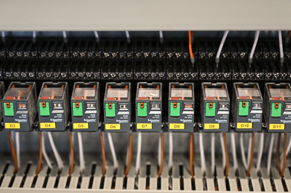
Reverse protection is one element of a chain, and the chain is what gets tested.
Fuse or PTC. Limits fault current if the pass element fails short. A resettable PTC is common; a fuse is more definitive.
TVS clamp. Absorbs surge energy per IEC 61000-4-5. It protects against a transient, not against a reversed supply.
Inrush limiting. A large input capacitor looks like a short circuit at power-on. Without limiting, the inrush current trips the upstream breaker or welds a connector.
Common-mode choke and X/Y capacitors. For conducted emissions and for surviving EFT per IEC 61000-4-4.
Undervoltage lockout. Keeps the device off, rather than oscillating, when the input is below the usable threshold.
Hold-up capacitance. Bridges a brief dip so the switch does not reboot when a contactor closes.
| Fault | Duration | Handled by | What it looks like if unprotected |
|---|---|---|---|
| Reverse connection | Minutes to hours | Series pass element | Dead device, sometimes with a scorched PCB |
| Surge (1.2/50 µs) | Microseconds | TVS plus layout | Latched-up controller or destroyed front end |
| EFT burst | Milliseconds, repeated | Choke, capacitors, TVS | Random resets during contactor switching |
| Inrush | Milliseconds at power-on | NTC, active limiter, or resistor bypass | Breaker trips, connector pitting |
| Brownout | Seconds | Undervoltage lockout plus hold-up | Repeated reboot cycles, corrupted configuration |
The mistake is to test it once, on one unit, at room temperature.
A defensible test sequence:
Reverse the input at nominal voltage and hold it for at least ten minutes. The device must remain off and undamaged, and the pass element must not exceed its thermal rating.
Reverse the input at the top of the range. This is the case that kills marginal designs, because the blocking element sees the highest voltage stress.
Reverse, then correct, then verify full function. A device that survives but comes back with a corrupted configuration has not passed.
Repeat at the temperature extremes. A P-channel MOSFET's Rds(on) rises with temperature, and a marginal design that passes at 25 °C can fail at 70 °C.
Confirm the upstream protection did not operate. If the reverse test blew the fuse, the pass element failed short and the "protection" was the fuse.
Warning: Never test reverse polarity on a device connected to a live network or to field wiring. The test is a deliberate fault injection, and it belongs on a bench with an isolated supply and a current-limited source.
Six questions that separate a datasheet from a design.
What is the input range, and is it continuous or transient? "9–60 VDC operating, 70 V for 1 s" is a specification. "9–60 V" with no qualifier usually means operating.
What is the reverse protection element? Diode, Schottky, P-channel MOSFET, or ideal diode controller — the answer tells you the heat and the drop.
What happens on a sustained reverse connection? The device should be undamaged, not merely "protected".
Which EMC standards were applied to the input port? IEC 61000-4-5 for surge and 61000-4-4 for EFT are the relevant ones for a DC input on industrial equipment.
What is the inrush current, and how long does it last? This decides whether the upstream breaker will hold.
What is the hold-up time at the bottom of the range? A device that reboots on a 20 ms dip is not suitable for a site with large motor loads.
The answers are usually in the EMC test report rather than the datasheet, so ask for the report. For Rayin's DIN-rail industrial switches, the published figures cover port count, housing, operating temperature and DC input; the protection topology and the EMC report should be requested per model, because they are not interchangeable across a product family.
Dual-input industrial switches usually OR two supplies through steering diodes or MOSFETs, and the reverse protection has to work per input rather than per device.
Two consequences:
A reversed connection on one input must not drag down the other. If both inputs share a single blocking element, a fault on one can take the whole device offline even though the second supply is healthy.
The ORing element also sets the minimum operating voltage. Two diode drops in series reduce the usable input window at the bottom of the range, which is exactly where a 12 V battery system spends its worst moments.
This is worth checking explicitly when a device claims both wide input and dual redundant inputs: the two features compete for the same millivolts at the low end.
Does the input protection also handle overvoltage?
No. They are separate functions. Reverse protection blocks current flowing the wrong way; overvoltage protection clamps or disconnects when the voltage exceeds a threshold. A device wired correctly but connected to a 90 V supply is an overvoltage event, and it needs a TVS or an input disconnect to survive it.
Why use a MOSFET instead of a diode for reverse protection?
Heat. A silicon diode drops about 0.7 V, so at 2 A it dissipates 1.4 W inside a sealed, fanless enclosure. A P-channel MOSFET with a low on-resistance drops tens of millivolts, which is negligible thermally and leaves more of the input range for the regulation stage.
Is 9–60 VDC a real requirement or a marketing number?
It is a real requirement on industrial sites. A 12 V battery system sags below 10 V during cranking, a 48 V telecom bus reaches 60 V during equalise charge, and long cable runs lose another volt or two. A device that only accepts a nominal voltage will drop out on a site where nothing is faulty.
What happens if the input is reversed on a device without protection?
Usually the input capacitor or the TVS fails short, which then takes out the upstream fuse. On some designs the failure is a fire risk. This is why reverse protection is a safety item and not a convenience feature, and why it is tested at the top of the input range rather than at nominal.
Can reverse voltage protection be added externally?
Yes, with an inline module or a Schottky in the supply lead, but it adds a component in the field where nobody can inspect it. The better answer is to specify the protection inside the device and treat an unprotected DC input as a fault in the product, not in the installation.
How to Read a Hardened Switch Spec Sheet Without Getting Fooled
Wide-Temperature Industrial Switches: Protection for Harsh Environments
Best Industrial Ethernet Switch: How to Choose for Harsh Sites
PoE Switch Power Calculation: Avoiding an Insufficient Supply
About the author: Sara — Sara is a Customer Manager at Rayin with over 10 years of experience in the communications field. In her free time, she enjoys badminton and swimming.
About Rayin: Shenzhen Rayin Technology Co., Ltd. — Company Profile