An industrial switch housing is a functional component, not a cosmetic one: on a fanless switch the case is the only path heat has to leave the silicon, and it is the only barrier between the electronics and the electrical noise around them. Rayin (Shenzhen Rayin Technology) is a manufacturer of GPON OLTs and industrial Ethernet switches. You can tell which kind of box you are being sold by asking four questions — what the case is made of, how the die is coupled to it, how it is grounded, and which immunity standard it was tested against.
On a fanless design, the enclosure is the heatsink. Aluminium alloy conducts roughly 150–200 W/m·K (industry-typical), against about 45–50 W/m·K for carbon steel — a three-to-four-fold difference in how fast heat leaves the case.
Ingress protection and thermal headroom trade against each other: an IP67 shell (IEC 60529) has no vent path, so sealed designs usually need ambient derating where an IP40 vented case would not.
EMC is a measurable claim, not a look. Ask for the immunity standard and level — IEC 61000-6-2 for industrial environments, with IEC 61000-4-2 ESD and IEC 61000-4-3 radiated immunity behind it.
In an office switch, the enclosure holds the board and little else. Air moves through vents, a fan pushes it across a heatsink, and the plastic shell contributes nothing thermally. Take the fan away — which is what a −40 to 75 °C industrial design does, because a fan is the single most likely part to fail — and conduction becomes the only cooling mechanism left.
Heat now has to travel from the switch die, through the package, through a thermal pad or bracket, into the case wall, and out to the air or to the DIN rail. Every one of those steps adds thermal resistance, and the sum decides the junction temperature at your worst-case ambient. Industry-typical silicon limits sit around 110–125 °C junction; the whole design exercise is keeping margin below that at 75 °C ambient rather than 25 °C.
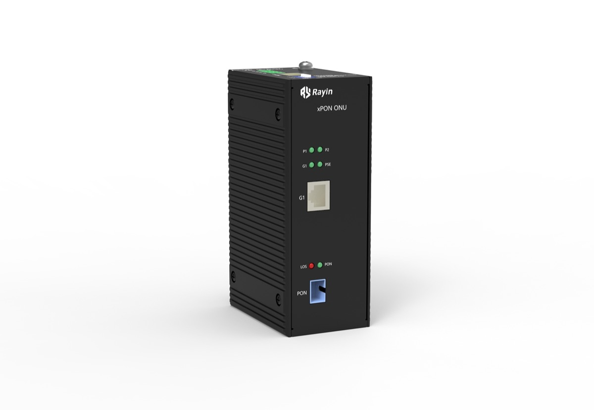
That is why a heavier box is not automatically a better box, but a coupled box is. Look for evidence of a deliberate path: a machined boss or bracket that contacts the SoC area, a thermal pad with a specified conductivity, and finning or ribbing on the outside surface to increase the area that touches air.
Four checks, in order of how much they tell you.
| Check | What a functional design looks like | What a decorative shell looks like |
|---|---|---|
| Material | Aluminium alloy case, or steel with an internal heat spreader | Thin steel or plastic, uniform wall, no spreader |
| Coupling | Thermal pad / bracket visibly contacting the SoC region | Air gap between board and case |
| Surface area | External fins or ribs, or the DIN-rail foot is metal and load-bearing | Smooth flat panels on all six sides |
| Documentation | θjc or junction-at-ambient figures, derating curve in the manual | "Wide temperature" with no curve |
DIN rail mounting matters more than it looks. EN 60715 defines the rail geometry, and a metal rail foot bolted to the case turns the rail and the cabinet backplate into an extra heatsink. A plastic clip defeats that entirely.
Shielding is the second job. A continuous metal case with conductive gaskets at the seams forms a Faraday cage, and a low-impedance ground path — usually a dedicated earth screw or the rail foot — drains induced current away from the PHY magnetics. Plastic housings need an internal metal shield or metallised coating to get anywhere near the same result, and the weakest point is almost never the wall: it is the seams, the cable entries and the unshielded gaps around status LEDs.
The practical way to separate marketing from engineering is to ask which standard was tested and at what level:
| Requirement | Typical industrial reference | What to request |
|---|---|---|
| ESD | IEC 61000-4-2 | Contact and air discharge levels, e.g. ±6 kV / ±8 kV |
| Radiated RF immunity | IEC 61000-4-3 | Field strength in V/m, commonly 10 V/m |
| Generic immunity | IEC 61000-6-2 | Full test report, not a self-declaration |
| Emission | IEC 61000-6-4 / EN 55032 | Class A or Class B limit |
| Substation duty | IEC 61850-3, IEEE 1613 | Only if the site is a substation |
Ask for the report, not the logo. A self-declared statement of conformity costs nothing to write; a third-party report names the lab, the date and the levels.
Is a metal housing always better than plastic? For a fanless industrial switch, yes in practice: metal gives both a conduction path and shielding. Plastic can be engineered with internal shields, but it still needs a separate route for heat to leave the enclosure.
Does IP67 make a switch harder to cool? Usually. A sealed IP67 enclosure (IEC 60529) removes the convection path a vented IP40 case relies on, so the same electronics will run hotter or need ambient derating. Choose the lowest IP rating the site actually requires.
Why does the DIN rail matter thermally? A metal rail foot couples the case to the rail and the cabinet backplate, adding surface area. It turns the whole cabinet into part of the cooling path rather than leaving the case alone.
What is a good junction temperature margin? Industry-typical silicon limits sit near 110–125 °C junction. Aim for meaningful margin below that at the maximum ambient you actually expect, and ask the vendor for the derating curve.
Which EMC numbers should I put in a tender? Name IEC 61000-6-2 as the generic immunity standard, then specify IEC 61000-4-2 ESD levels and IEC 61000-4-3 field strength, and require a dated third-party test report.
MTBF is not lifespan: from 200,000 hours to an annual failure rate
Industrial vs commercial Ethernet switches: where the money goes
About the author: Sara is a Customer Manager at Rayin with over 10 years of experience in the communications field. In her free time, she enjoys badminton and swimming.
About Rayin: Shenzhen Rayin Technology Co., Ltd. — company profile