A link that tested clean on the bench usually dies in the cabinet because someone pulled a patch cord into a bend tighter than its minimum bend radius, and the longest PON wavelength pays for it first. Most of these faults are macrobend loss, not a bad splice or a dirty SC APC connector, and getting the fiber bend radius wrong at a tray edge explains the whole outage.
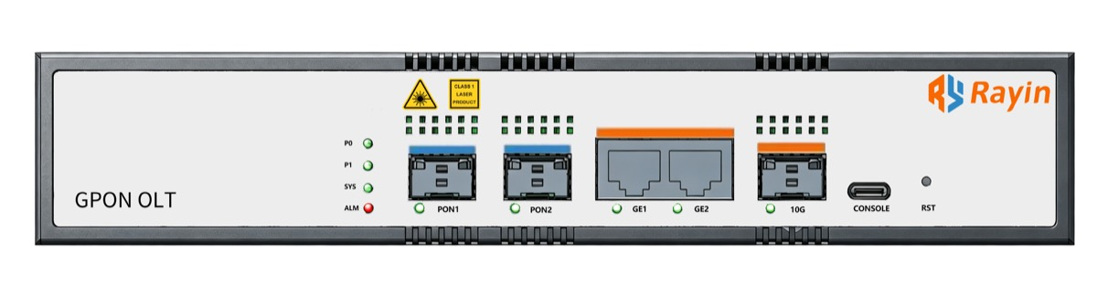
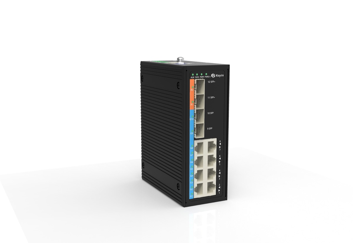
Rayin (Shenzhen Rayin Technology) is a manufacturer of GPON OLTs and industrial Ethernet switches.
Macrobend loss climbs with wavelength. The same tight coil that costs almost nothing at 1310 nm costs far more at 1550 nm, which is why a link passes a 1310 nm source test and then fails once live traffic at 1490 nm is on the fiber.
The minimum bend radius is a construction rule, not a datasheet decoration. Standard single-mode patch cord is commonly dressed at a 30 mm radius, industry-typical; a cable tie pulled flat against a manager is enough to cross that line.
Triage cheapest first: re-measure at the working wavelengths, open the door and look, relax the ties and re-dress, then bring in a VFL and OTDR. Leave the power-budget worksheet shut until the physical layer is clean.
Anyone who has commissioned a PON knows the pattern. On the bench, jumpers laid straight and a source at 1310 nm, the link measures comfortably inside budget. Coil the slack into the cabinet, click the door shut, and the ONU will not register. The electronics never changed. Geometry did.
A macrobend is a bend large enough that light at the outer edge of the core escapes total internal reflection. ITU-T G.984.2 puts the GPON downstream in the 1480-1500 nm band and the upstream near 1310 nm, with 1550 nm held for an overlay; all three sit in the single-mode window described by ITU-T G.652 and measured under the IEC 60793 series. Bend a fiber and power leaks at the turn. The longer the wavelength, the more of the mode travels outside the core, and the more it leaks. Industry-typical measurements put 1550 nm at roughly 1.5 to 2 times more bend-sensitive than 1310 nm at the same radius.
That wavelength dependence is why the fault hides. A 1310 nm visual fault locator or a single-wavelength source excites the least sensitive window. Live GPON arrives downstream at 1490 nm, and an OTDR or video overlay rides at 1550 nm. A coil that looked fine at 1310 nm quietly adds a fraction of a dB per turn at 1490 nm and more at 1550 nm. Six tight turns in one slack loop eat the margin the link needed.
These are not two grades of "good". They are built for different bends. ITU-T G.652 is the standard single-mode fiber in the outside plant and most feeder and distribution cable — cheap, ubiquitous, and fine when you give it room. ITU-T G.657 is the bend-insensitive family, split into categories matched to how tight the turn is, and it exists for the places a cabinet denies you room: drop cable, indoor routing, the last metre behind a patch panel.
| Fiber | Typical minimum bend radius (industry-typical) | Where it belongs | Where it is wasted |
|---|---|---|---|
| ITU-T G.652 standard single-mode | ~30 mm for a dressed patch cord, or about 10 times cable diameter under static load | Feeder, distribution, outside plant, any gentle run | A 1U cabinet with a short slack loop and a right-angle manager |
| ITU-T G.657, Category A | ~10 mm, splices to G.652 | Drop cable, FTTH indoors, tight indoor turns | Long outdoor spans where bend performance buys nothing |
| ITU-T G.657, Category B | ~7.5 mm, the tightest class | The last centimetres behind an ONU or inside a closure | Anywhere a 30 mm radius fits and cost matters |
Two field notes. G.657 Category A is designed to fuse to G.652 without a mode-field mismatch — both sit near 9.2 microns at 1310 nm, industry-typical — so an installer can put bend-insensitive fiber only at the tight end. Category B trades bend tolerance for a smaller mode-field diameter, and dropping it into a long G.652 run can raise fiber splice loss at the joint; keep it to short jumpers. The IEC 60793 series defines the test methods used to quote these radius figures.
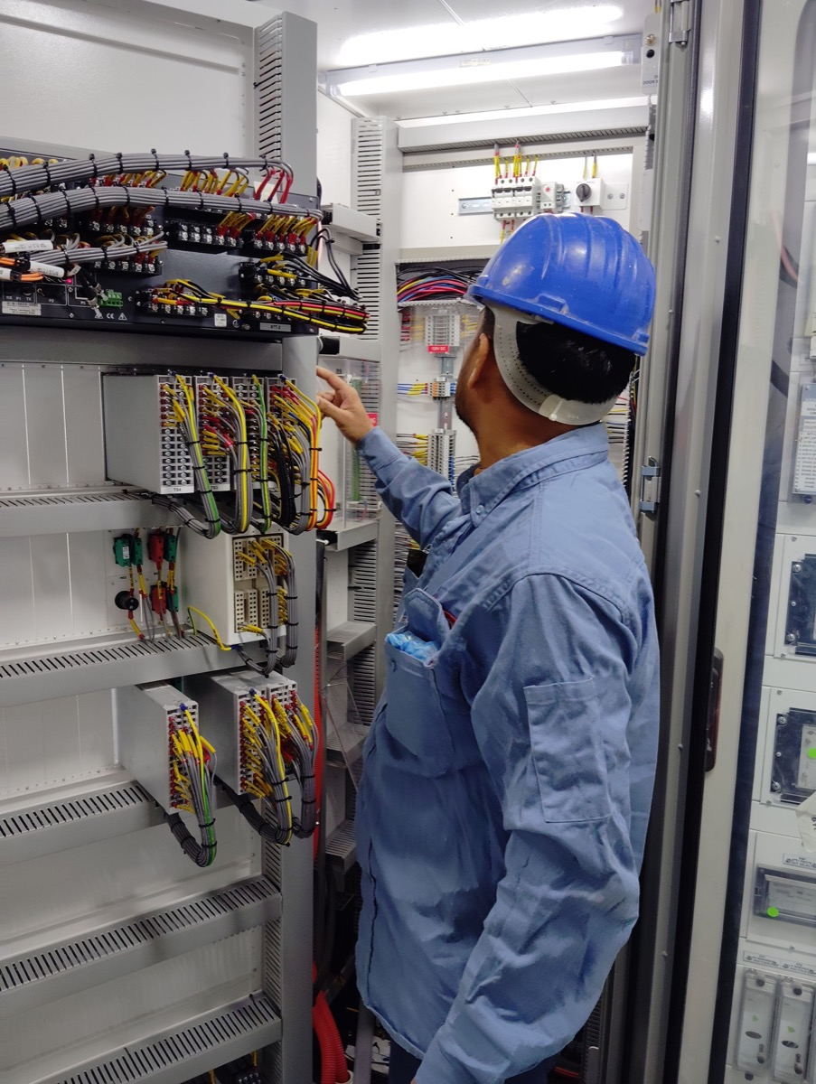
Nearly every "passed the test, failed in the cabinet" ticket comes down to one of four habits, and all four are visible with the door open.
| Habit | What it does to the fiber | Symptom at the ONU |
|---|---|---|
| Zip tie pulled flat on a slack loop | Pinches a 30 mm loop to a few mm at the tie | Level drops a few dB; registration becomes intermittent |
| Slack coiled below the guided radius | Adds a fraction of a dB per turn, worse at 1490/1550 nm | Downstream marginal, upstream fine, worse in warm weather |
| Right-angle manager or hard 90-degree tray edge | Forces a corner instead of a sweep | One high-loss event an OTDR reads as a point fault |
| Patch cord bent back against an SC APC connector boot | Kinks the fiber at the ferrule, can crack it | High optical return loss plus a bad reflectance reading |
The fourth is also a reflection problem. An angled 8-degree end face pushes reflected light out of the core, and a clean connector holds return loss better than -60 dB, industry-typical; a kink or dirt at the boot throws that away and shows up as reflectance on an OTDR trace. Optical return loss is not insertion loss. Confusing the two is why a bent patch cord near the ferrule gets called a bad connector and swapped twice before anyone looks at the bend.
Work cheap to expensive. Do not open the power-budget worksheet until the physical layer is clean. A sequence that actually closes these tickets:
| Step | Action | What the result means |
|---|---|---|
| 1 | Re-measure with a power meter at 1490 nm and 1550 nm, not a 1310 nm source | A wavelength-dependent gap points straight at a macrobend |
| 2 | Open the cabinet and photograph the routing before touching anything | Records the as-built condition and the over-tight tie |
| 3 | Cut the suspect ties, relax the loop to a 30 mm radius, sweep the hard corner | If level recovers 1-3 dB, industry-typical, you have found it |
| 4 | Shine a visual fault locator (650 nm) along the jumper and watch the bend | A bright leak localises the fault to a centimetre |
| 5 | Run an OTDR at 1550 nm to separate a bend from fiber splice loss and a reflectance event | A step with no reflective spike is a bend; a spike is a connector |
| 6 | Only now re-check the budget with the as-built loss values | Confirms the margin is genuinely back, not briefly |
Two boundary conditions. A 650 nm visual fault locator makes macrobends glow red because visible light is far more bend-sensitive than the 1310 nm window — use it to find the spot, not to judge the loss a live link will see. And an OTDR at 1550 nm exaggerates a bend relative to 1310 nm; that is a feature, because it makes the culprit obvious, but do not quote the 1550 nm figure as the 1490 nm operating penalty. The fiber bend radius you defend at the tray is a construction number, and the measurement is how you prove the fiber now meets it.
Why does my PON link test fine at 1310 nm but fail with live traffic?
Because 1310 nm is the least bend-sensitive PON window. A tight coil that leaks almost nothing at 1310 nm can add a fraction of a dB per turn at 1490 nm and more at 1550 nm. Always re-measure at the working wavelengths before blaming the optics.
Can I just pull the slack loop tighter to make it fit?
No. A slack loop exists to keep the fiber above its minimum bend radius, so flattening it defeats the point. If space is short, re-route through a proper radius guide or use a bend-insensitive jumper at that end. At Rayin we see bent slack loops in support photos more often than failed optics.
Does a dirty SC APC connector cause the same symptoms?
It can, but the signature differs. Dirt or a kink at the ferrule raises optical return loss and shows a reflective spike on an OTDR trace, while a macrobend shows a clean step with no reflection. Clean and inspect the end face first, then look at the bend.
Should I swap the whole jumper for G.657 bend-insensitive fiber?
Only where the turn is genuinely tight. G.657 Category A splices to G.652 without a mode-field penalty, so a short bend-insensitive tail at the cabinet is sensible, but a long G.652 run gains nothing. Check fiber splice loss at any mixed joint.
Is a 30 mm minimum bend radius a hard standard?
It is an industry-typical construction rule for standard single-mode patch cord, roughly 10 times the cable diameter under static load, not a single clause you can cite. G.657 bend-insensitive fiber is commonly rated tighter, around 7.5 to 10 mm. Follow the cable maker's figure over any rule of thumb.
A cabinet is a hostile place for single-mode fiber because it rewards tidy, tight work and punishes it at the wavelengths PON actually uses. The fix is almost never a new optic: measure at 1490 nm and 1550 nm, open the door, cut the over-tight tie, re-dress the slack to a defensible radius. Rayin builds the GPON OLTs and industrial Ethernet switches at either end of these links, and the field faults we hear about are far more often a bent jumper than a failed port. Get the geometry right and the "good" link stays good after the door closes.
The wavelength plan, fiber categories and measurement context above come from public industry sources — ITU-T G.984.2 (the GPON wavelength bands), ITU-T G.652 and ITU-T G.657 (single-mode fiber and the bend-insensitive categories), and the IEC 60793 series (optical fiber measurement methods). Only series names and category labels are used; no clause numbers are quoted. The method, worked examples and wording are written by Sara, who checked each figure against those sources before publication. Anything presented as an industry-typical value — minimum bend radius, per-turn loss, return loss and mode-field diameter — is labelled as such and should be checked against the cable maker's data sheet; nothing here is a measured figure from a Rayin product unless it says so.
About the author: Sara — Sara is a Customer Manager at Rayin with over 10 years of experience in the communications field. In her free time, she enjoys badminton and swimming.
About Rayin: Shenzhen Rayin Technology Co., Ltd. — Company Profile