The fiber optic cable installation method you choose decides your failure rate for the next twenty years, not your material cost. Aerial goes up in a week and fails on the first ice storm. Direct burial costs three times more upfront and then quietly rots where nobody can see it. Duct sits in between and depends almost entirely on whether the ducts were built properly a decade before anyone thought about fiber. Pick by failure mode and maintainability, then check that the resulting loss still fits inside your PON budget.
Rayin (Shenzhen Rayin Technology) is a manufacturer of GPON OLTs and industrial Ethernet switches.
Four methods, four different failure modes: wind and vehicle strike (aerial), water ingress and rodent damage (buried), duct collapse and blocked sub-ducts (duct), and bend loss at the last metre (indoor).
On ITU-T G.652.D single-mode fiber the glass itself loses at most 0.35 dB/km at 1310 nm and 0.20 dB/km at 1550 nm — so a 2 km feeder run costs you 0.7 dB of glass loss, while one dirty connector costs 0.3 dB to 0.5 dB. The connectors usually matter more than the distance.
Every method adds splices at different points. At 0.1 dB per fusion splice, a route with six extra closures has already spent 0.6 dB of a 28 dB Class B+ budget before the splitter is even counted.
Start with the comparison nobody puts in the tender document.
| Method | Typical span or segment | Dominant failure mode | Mean time to locate a fault | Best fit |
|---|---|---|---|---|
| Aerial | 40–60 m between poles | Wind vibration, ice load, vehicle strike, tree contact | Hours — the route is visible | Suburban and rural distribution, fast build-out |
| Duct | 500–1000 m between chambers | Blocked or collapsed duct, water pooling, sub-duct friction | Half a day to a day — needs rodding and pulling | Urban areas with existing duct banks, campus backbones |
| Direct buried | 500–2000 m per trench run | Excavator strike, rodent chew, water ingress at joints | Days — needs locator and test pits | Long rural feeders, areas with no poles or ducts |
| Indoor / riser | One floor to one building | Bend loss at tight corners, crushed cable behind drywall | Hours, but inside someone's premises | MDU risers, in-building last drop |
Read that table as a maintenance document, not a shopping list. The row that matters is "mean time to locate a fault". An aerial fault is usually a matter of walking the route and looking up. A buried fault on a 2 km run means a locator, a test pit, and a permit — and the customers stay dark for the whole process.
Installation labour dominates the budget on all four, but in different proportions. Aerial is mostly pole hardware and a bucket truck. Duct is mostly pulling tension and chamber work. Direct burial is mostly trenching, sand bedding, and warning tape. Indoor is mostly fire-stop and cable management, which is cheap per metre and expensive per building.
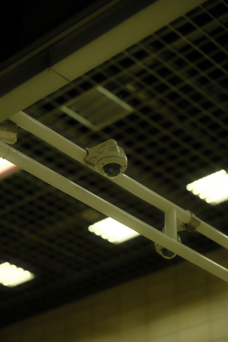
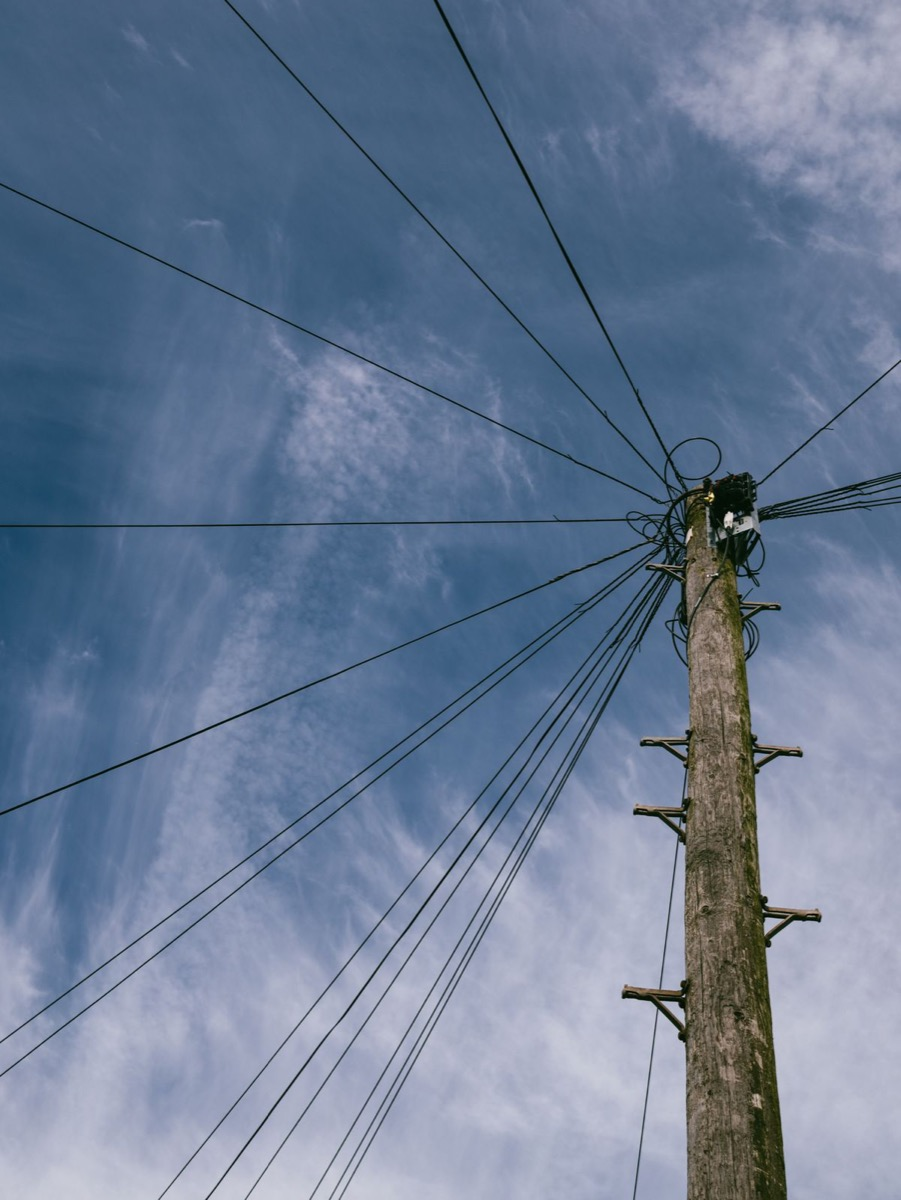
An aerial fiber cable lives on someone else's infrastructure. That single fact explains most of its failure statistics.
The cable is suspended between poles that were designed for a messenger wire, not for a fiber bundle with a steel strength member. Every gust puts the cable into a vibration mode; the attachment clamps concentrate that movement at one point. Add ice, and the load goes up by an order of magnitude. The result is not usually a clean break — it is a slow attenuation drift that a technician notices months later when a subscriber at the end of the run starts complaining about IPTV freezing.
Two details separate an aerial route that lasts fifteen years from one that lasts four:
Span length discipline. Keep urban distribution spans inside the pole loading calculation, not inside what a crew can physically reach. Longer spans look cheaper per metre and cost more per fault.
Dead-end and suspension hardware matched to the cable's rated tension. A clamp sized for a 12-fiber figure-8 will not hold a 144-fiber ADSS cable.
Also budget for the trees. On rural routes, tree contact is the single largest cause of aerial damage, and no amount of cable quality survives a branch that grows into the span every summer. If the route cannot be kept clear, aerial is the wrong answer regardless of cost.
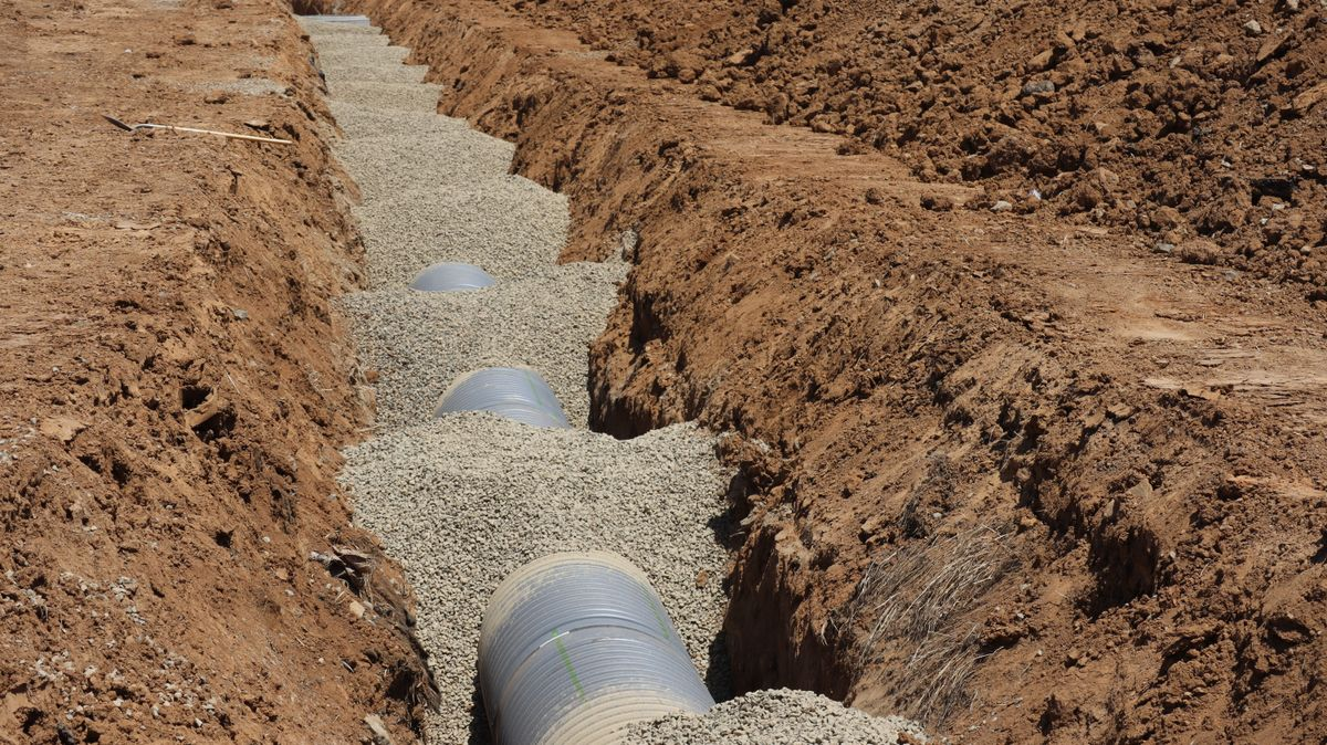
Underground fiber optic cable is the default choice for anything that must survive a storm season without a maintenance crew on standby. The trade is straightforward: you pay for excavation once and then stop thinking about the route.
What usually goes wrong is not the cable. It is the duct.
Duct occupancy planned at 40%, not 100%. A duct filled to capacity cannot be re-pulled, so the first cable fault becomes a new trench.
Sub-duct for anything you intend to upgrade. Blowing a 12-fiber cable into a 40/33 mm sub-duct leaves room for a second cable later; pulling it directly into a 100 mm duct does not.
Chamber drainage. Water in a chamber is not automatically fatal to a filled cable, but standing water plus a poorly sealed closure is how water trees start inside the loose tube.
In city centres, duct is almost always cheaper than trenching, because the trench already exists and the permit to open the road does not. In greenfield suburbs it often is not, because the duct bank has to be built first and paid for by somebody.
Direct buried fiber cable removes both the pole and the duct, and in exchange it removes every opportunity to inspect the route.
Armoured construction is the reason it works at all. Corrugated steel or aluminium tape under the jacket resists soil pressure and rodent attack; a properly bedded trench with sand or screened backfill protects the armour. Skip either, and the cable survives commissioning and fails in year three at a point nobody recorded.
Warning: A buried route without an as-built drawing with GPS coordinates and depth is not a maintainable route. The cable will outlive the person who remembers where it went.
Three habits keep buried plant alive: warning tape 30 cm above the cable, trace wire on every non-metallic run, and a joint closure that is re-enterable rather than potted. The first two protect against excavators; the third protects your splice loss budget when a repair is needed.
Indoor work is where the cheapest mistake in the whole plant gets made: bending a standard G.652.D cable around a corner tighter than its minimum bend radius. Macrobending loss does not announce itself. It appears as a link that works at 1310 nm and fails at 1490 nm, or as an ONU that registers on a short drop and drops out on a long one.
Bend-insensitive fiber changes the arithmetic. ITU-T G.657.A1 is specified for a 10 mm minimum bend radius and G.657.A2 for 7.5 mm, against roughly 30 mm for plain G.652.D. For in-building drops behind skirting and around door frames, that difference is the whole argument for spending more per metre.
Fire rating is the other non-negotiable. Riser and plenum routes need the cable jacket rated for the space it passes through, and the fire-stop at each penetration has to be reinstated after every subsequent cabling job. A riser that passes inspection on day one and is penetrated six more times over three years is a code problem waiting for an inspector.
Cable construction is not a preference; it is a consequence of the route and the environment. That is why fiber optic cable types cannot be chosen from a catalogue without knowing the route first.
| Route condition | Construction to specify | Why |
|---|---|---|
| Overhead on poles, long span | ADSS or figure-8 with messenger | Self-supporting or messenger-borne; rated tension matters more than fiber count |
| Overhead near HV lines | All-dielectric (ADSS) | No metallic path, so no grounding or flashover path |
| In duct, long pull | Low-friction jacket, non-armoured | Pulling tension and friction, not crush resistance, is the limit |
| Direct buried, rodent risk | Corrugated steel or aluminium armour | Mechanical protection without conduit |
| In-building riser | Tight-buffer or bend-insensitive, riser-rated jacket | Bend radius and fire rating govern |
| Outdoor-to-indoor transition | Outdoor-rated to the entry point, then transition | Water blocking must not be relied on indoors |
One rule overrides the table: never run an indoor-rated cable outdoors, and never bring an outdoor cable jacket into a plenum space without a proper transition. The failure is not immediate, which is exactly why it gets missed.
This is where a civil decision becomes an active-equipment decision.
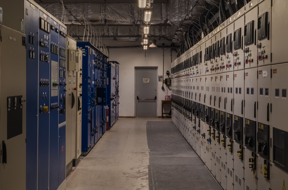
GPON as defined in ITU-T G.984.2 gives a Class B+ optical budget of 28 dB between the OLT port and the ONU. That number has to absorb everything: fiber attenuation, splices, connectors, splitter insertion loss, and a margin for ageing and repair.
Run the arithmetic on a 2 km feeder:
Fiber: 2 km × 0.35 dB/km at 1310 nm = 0.7 dB. At 1490 nm downstream, 2 km × 0.20 dB/km = 0.4 dB.
Splices: six fusion splices at 0.1 dB = 0.6 dB.
Connectors: four mated pairs at 0.3 dB = 1.2 dB.
Splitter: a 1:32 split is 16.5 dB of theoretical splitting loss, plus roughly 1 dB excess loss.
Margin: 3 dB for ageing, repairs and temperature.
Total: about 22.8 dB of the 28 dB budget, before the drop cable reaches the subscriber. That leaves 5 dB for the last few hundred metres and the subscriber's own patch cords — which is workable, and which is also why an extra closure in the middle of the run is not a trivial change.
Now compare the methods. Aerial routes tend to accumulate splices at every pole where a slack loop was needed. Buried routes accumulate them at every joint closure, and each closure is a water-ingress candidate. Duct routes accumulate them at chambers. None of these is free: at 0.1 dB per splice, the difference between four and ten splices is 0.6 dB — small on paper, decisive when the splitter ratio is already at 1:64.
Tip: Design the ODN at 80% of the budget, not 95%. The remaining 20% is what pays for the repair splice you will need in year four, and for the splitter ratio upgrade you will want in year six.
Once the ODN is fixed, the active side has to be sized against it. Three parameters move together:
Splitter ratio. 1:32 costs 16.5 dB and 1:64 costs 20.5 dB of theoretical splitting loss. Ten kilometres of aerial route with ten splices cannot afford 1:64 on a Class B+ budget; the same distance on a clean duct route with four splices usually can.
PON port count. Longer, lossier ODN routes push you toward fewer subscribers per port but more ports per site, which changes the OLT form factor you need.
ONU receive sensitivity. A receiver specified near the edge of the class leaves no room for a marginal connector. Choosing an ONU with margin is cheaper than re-terminating a route.
For FTTH builders sizing the active side against a real ODN, Rayin's mini GPON OLT line covers 1-port and 2-port models with 1:128 splitting per PON port — enough headroom for a staged build where the first cabinets go live long before the last subscribers are connected.
The practical sequencing is: fix the route and the splice plan first, compute the budget second, then choose splitter ratio and OLT port count. Doing it in the other order is how projects end up with a 1:64 splitter and a link that only works in cool weather.
| Check | Pass criterion | Consequence of skipping |
|---|---|---|
| Route as-built | Drawing with GPS, depth, and closure positions | Every future fault becomes a search operation |
| Splice loss record | Each fusion splice ≤0.1 dB, bidirectional OTDR stored | A drifting link has no baseline to compare against |
| Connector cleanliness | Every connector inspected and cleaned before mating | 0.3–0.5 dB per dirty end, invisible in the budget |
| Bend radius | No bend tighter than the cable's rating (10 mm for G.657.A1) | Wavelength-dependent loss that only shows at 1490 nm |
| Duct occupancy | ≤40% after pulling | No path for the next cable or a re-pull |
| Budget margin | ≥20% of the class budget unallocated | No room for repair splices or a splitter upgrade |
Which fiber optic cable installation method has the lowest failure rate?
Duct, when the duct bank is sound. The cable never sees wind load, excavation, or sunlight, and faults are usually confined to chambers that can be opened. Direct burial is comparable in the first decade but degrades faster once water reaches a closure. Aerial has the highest fault rate and the fastest fault location.
How much optical loss should I allow per kilometre?
On ITU-T G.652.D single-mode fiber, budget 0.35 dB/km at 1310 nm and 0.20 dB/km at 1550 nm as the specified maximum. Real installed cable usually measures better, but planning against the standard maximum is what keeps a Class B+ 28 dB budget honest once splices and connectors are added.
Can I run aerial fiber cable on existing power poles?
Usually yes, with two conditions: the pole owner permits attachment, and the span and hardware are rated for the cable's tension and wind load. All-dielectric self-supporting cable avoids grounding work near high-voltage lines. Never attach without a loading calculation — the pole was designed for a different load case.
Does direct buried fiber cable need conduit?
Not always, but armoured cable in a properly bedded trench with warning tape and a trace wire is the minimum. Conduit or sub-duct pays for itself the first time the route has to be re-entered, because pulling a new cable beats digging a new trench.
How do I know whether my ODN still fits the OLT budget?
Add fiber loss, splice loss, connector loss, splitter insertion loss and a 3 dB margin, then compare the total to the class budget — 28 dB for Class B+ under ITU-T G.984.2. If the sum exceeds 80% of the budget before the drop cable is counted, reduce the splitter ratio or re-route. Rayin sizes its GPON OLT ports against this same budget, so the calculation transfers directly to the port plan.
Fiber Optic Cable Splicing: Fusion vs Mechanical vs Pre-Terminated
How to Test a PON Link: OLT Test with Power Meter, VFL and OTDR
About the author: Sara — Sara is a Customer Manager at Rayin with over 10 years of experience in the communications field. In her free time, she enjoys badminton and swimming.
About Rayin: Shenzhen Rayin Technology Co., Ltd. — Company Profile