Power fails first because data only needs the signal to arrive, while power needs the voltage to arrive, and every metre of conductor spends voltage. A link can be error-free at 90 metres and still be unable to run a camera, because the two budgets are different budgets.
Rayin (Shenzhen Rayin Technology) is a manufacturer of GPON OLTs and industrial Ethernet switches.
IEEE 802.3af guarantees 12.95 W at the powered device from a 15.4 W source; the difference is the allowance for loss in the channel. That margin is what cable quality spends.
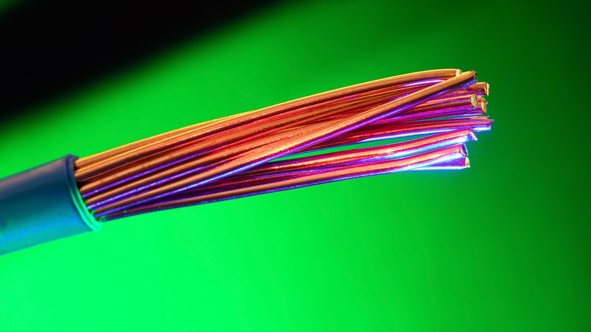
Copper clad aluminium cable has roughly 1.5 to 1.6 times the DC resistance of solid copper of the same gauge, and that multiplier applies directly to voltage drop.
A run that works at 30 metres can fail at 90 metres with the same hardware, and a camera with infrared and a heater can push a marginal run over the edge only at night.
Data tolerates attenuation and noise; power does not tolerate lost volts.
| PoE type | Source output at the PSE | Guaranteed at the powered device | Current drawn |
|---|---|---|---|
| IEEE 802.3af (Type 1) | 15.4 W | 12.95 W | Up to 350 mA per pair set |
| IEEE 802.3at (Type 2) | 30 W | 25.5 W | Up to 600 mA per pair set |
| IEEE 802.3bt (Type 3) | 60 W | 51 W | Up to 600 mA per pair set |
| IEEE 802.3bt (Type 4) | 100 W | 71 W | Up to 960 mA over four pair sets |
The gap between the first two columns is not generosity — it is the loss budget for the channel, and it is the only headroom you have. A receiver will happily decode a signal that has lost most of its amplitude; a camera will simply not start if the voltage at its input is below what it needs.
The numbers that matter at the far end are the minimums the standard works to: the source is specified to deliver at a stated minimum voltage, and the powered device is specified to operate down to a stated minimum. Everything in between is spent on the copper.
Ohm's law, with a loop rather than a single conductor, because the current goes out and comes back.
| Conductor | DC loop resistance, industry-typical | Drop at 350 mA over 100 m | Drop at 600 mA over 100 m |
|---|---|---|---|
| 24 AWG solid copper, two pairs carrying power | Around 9.4 Ω | Around 3.3 V | Around 5.6 V |
| 24 AWG aluminium-clad, two pairs | Around 14 to 15 Ω | Around 5 V | Around 8.5 V |
| 26 AWG thin stranded copper patch | Around 15 Ω | Around 5.2 V | Around 9 V |
| Any of the above plus a high-resistance crimp | Add 1 to 3 Ω | Add 0.4 to 1 V | Add 0.6 to 1.8 V |
Run the 802.3at case: 8.5 V lost over a 100 m CCA run, taken from the lower end of the source voltage range, lands the powered device below the voltage it needs. That is the whole failure, and it happens with a link that reports a clean gigabit connection. At 60 metres the same run has roughly 5 V of drop and works perfectly, which is why the fault looks intermittent and distance-dependent.
Three separate defects, often sold as one cable.
| Defect | What it does | How to spot it |
|---|---|---|
| Aluminium-clad conductors | 1.5 to 1.6 times the DC resistance of copper; more brittle; oxidises at the termination | Scrape and look at the conductor end: a silvery core under the copper-coloured cladding |
| Inflated AWG marking | Cable sold as 24 AWG that measures like 26 or 27 AWG, so the resistance budget is wrong from the start | Weigh a known length and compare with a known-good sample; check the printing against the specification sheet |
| Poor crimp or punch-down | Adds series resistance at one point, and can be intermittent with vibration and temperature | Measure loop resistance end to end and compare with the calculated figure for the length |
| Aluminium-clad used outdoors | Corrosion at the connector interface adds resistance over time | Rising failures in months 6 to 18 on the same runs |
Category cabling standards specify copper conductors, which is why copper clad aluminium sold as category cable is a specification problem and not only a performance one. This article is a diagnostic, not a purchasing recommendation: whatever you buy, ask for the conductor material and gauge in writing, and measure the loop before you energise critical loads.
Because the load is not constant.
| Load event | Extra power drawn | Effect on a marginal run |
|---|---|---|
| Infrared illuminators switch on at dusk | A few watts | Voltage drops further, sometimes below the camera's minimum |
| Heater element switches on in cold weather | Several watts | The largest single step in a camera's load profile |
| Pan-tilt-zoom movement | Motor current, briefly | Short spikes that a supply with no margin cannot absorb |
| All cameras on one switch doing it simultaneously | The sum of all of the above | A simultaneous reboot of every camera on the switch |
That last row is the diagnostic signature. Cameras that all reboot at dusk, on a switch whose total power budget is not exceeded, are telling you the per-port voltage is the problem rather than the total wattage.
Isolate in this order, because each step eliminates a whole class of cause.
| Order | Action | What the result tells you |
|---|---|---|
| 1 | Read the port counters: CRC errors, alignment errors, link flaps | Errors point at the physical channel; a clean counter with a dead powered device points at voltage |
| 2 | Move the device to a short patch cable at the switch | If it powers up, the long run is the problem |
| 3 | Move the same device to a different port on the same switch | If it still fails, the port is not the variable |
| 4 | Measure the DC loop resistance of the installed run | Compare with the calculated value for the length and material |
| 5 | Swap in a known-good copper run of the same length | If the fault follows the cable, you have the answer |
| 6 | Only then suspect the switch | Everything above is cheaper and more likely |
Why does a camera work at 30 metres and fail at 90 with the same switch?
Because voltage drop is proportional to length, while link quality is not. A 90 m run of high-resistance cable can deliver a perfect gigabit signal and still land below the camera's minimum input voltage, which is why the symptom is power loss rather than packet loss.
Is copper clad aluminium cable unsuitable for PoE, or just worse?
It is worse in a way that matters: 1.5 to 1.6 times the DC resistance of copper of the same gauge means proportionally more voltage lost per metre. Category component standards call for copper conductors, so it is also a specification issue where category compliance is required.
Can a bad crimp really cause a reboot?
Yes. A single high-resistance termination adds series resistance exactly where the current is highest, and it can be intermittent with temperature and vibration, producing reboots that appear random.
Do I need Cat6 instead of Cat5e to fix PoE drop?
Not necessarily. Conductor gauge and material drive DC resistance; the category marking describes transmission performance. A thick 23 AWG Cat6 run and a thin 24 AWG Cat5e run differ in resistance because of the conductor, not the category name.
Why do all the cameras reboot at the same time?
Usually because a shared load event — infrared at dusk, or a heater in cold weather — pushes every marginal run below its minimum at once. Check per-port voltage before assuming the switch has exceeded its total power budget.
PoE failures are voltage-budget failures, and the budget is spent by conductor material, gauge, length and terminations in that order. Measure the loop, isolate with a short patch, and check the port counters before replacing anything. Rayin publishes the PoE budget per port and per switch for its industrial PoE lines, which is the figure to compare against the calculated drop rather than the total wattage alone.
The power and transmission figures above come from public industry sources — IEEE 802.3af, IEEE 802.3at and IEEE 802.3bt (Power over Ethernet types, source output, guaranteed power at the powered device and per-pair-set current limits) and the TIA/EIA-568 cabling category specifications for conductor requirements. Loop resistance figures and drop calculations are industry-typical worked examples, not measurements of any specific cable product, and this article makes no cable brand or purchasing recommendation. The method, worked examples and wording are written by Sara, who checked each figure against those sources before publication. Nothing here is a measured figure from a Rayin product unless it says so.
About the author: Sara — Sara is a Customer Manager at Rayin with over 10 years of experience in the communications field. In her free time, she enjoys badminton and swimming.
About Rayin: Shenzhen Rayin Technology Co., Ltd. — Company Profile