A ground potential difference is a voltage you create yourself: two devices earthed at different points sit at different potentials, and the cable between them becomes the path that equalises them. Surge protection does not address it, because nothing is coming in from outside — the energy is already inside your installation.
Rayin (Shenzhen Rayin Technology) is a manufacturer of GPON OLTs and industrial Ethernet switches.
Surge is an external transient that a protector diverts to earth; a ground potential difference is a standing or slowly varying voltage between two earths, and it drives current continuously rather than in one spike.
The current path is usually the cable shield, and the first component to fail is the port PHY, because the isolation transformer is the weakest point in that path.
Before touching any earth connection, rule out CRC errors, then PoE voltage drop, then grounding. Most "earthing problems" are one of the first two.
Both damage ports, and they need different fixes, so separating them is the first diagnostic step.
| Aspect | Surge transient | Ground potential difference |
|---|---|---|
| Source | Lightning, grid switching, inductive load switching | Different earth electrode resistance, different bonding points, return currents in the protective conductor |
| When it happens | During a storm or a switching event | Continuously, or whenever large plant loads start and stop |
| Waveform | A fast transient lasting microseconds to milliseconds | A standing voltage, or a slow variation following the load cycle |
| What protects against it | A surge protective device that diverts to earth | Bonding the two earths together, or isolating the data path |
| Signature left behind | Often a dramatic single event, sometimes several ports at once | One or two ports dead, on a day with no storm anywhere near |
That last row is the one that identifies the problem. A single port that dies on a clear, quiet afternoon is not a lightning story.
A shielded cable is only a shield if the current it carries has somewhere else to go. When it does not, it becomes a conductor.
| Shield termination | Does it form a loop? | Where it works | Where it does not |
|---|---|---|---|
| Both ends bonded to local earth | Yes, if the two earths differ in potential | Short runs inside one cabinet, where both ends share the same earth bar | Between buildings or between distant cabinets |
| One end bonded, other end floating | No loop | The usual answer for runs between separate earth systems | Long runs at high frequency, where the floating end provides less shielding |
| Both ends through a capacitor or a hybrid bond | Controlled | Where shielding at radio frequency and isolation at power frequency are both needed | Never as a default without checking the design |
| Shield not connected at all | No loop, and no shield | Nowhere on an industrial site | Everywhere; this is the most common installation defect |
The path that does the damage runs from the higher-potential earth, along the shield, into the switch chassis, and through the port transformer to the signal pairs. IEEE 802.3 requires the twisted-pair PHY to be galvanically isolated from the cable side with a specified withstand voltage, which is exactly why the transformer is the component that absorbs this energy first — and why the port dies while the rest of the switch keeps running.
IEC 61000-5-2 gives installation and mitigation guidance covering earthing and cabling, and IEC 60364-5-54 covers earthing arrangements and protective conductors. Both point at the same practical activity: make the bond low impedance and measure it.
| Check | Method | Industry-typical target |
|---|---|---|
| Electrode resistance | Fall-of-potential measurement with an earth tester | Below 10 ohms for a general installation electrode; sensitive electronics sites commonly specify lower |
| Bond continuity | Low-resistance ohmmeter between the equipment earth point and the earth bar | Fractions of an ohm; anything measurable in ohms is a loose or corroded bond |
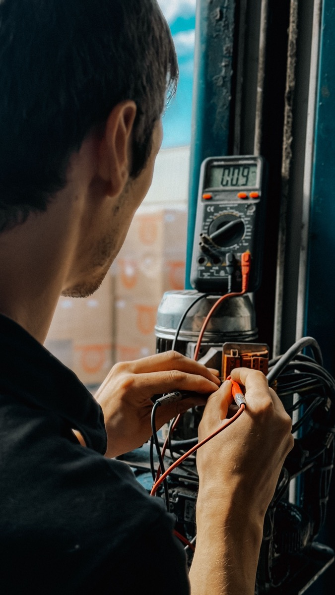
| Standing voltage between two earths | AC voltmeter between the two equipment earth points | Should be near zero with no load cycling; volts of difference under load cycling is the diagnostic |
| Bonding conductor size | Visual and mechanical check against the installation design | Sized so the bond, not the data cable, carries fault current |
The measurement that matters most is the one nobody takes: the AC voltage between the two earth points while the plant is running. Zero volts on a Sunday and four volts at shift start tells you the difference is load-driven, which points at a return current problem rather than at a bad electrode.
Because the mechanism has nothing to do with weather.
| Observation | What it usually means | What to do |
|---|---|---|
| Port dead after a quiet, dry day | Continuous shield current over time, or a load-cycle peak | Measure the standing voltage between the two earths under load |
| Failures cluster at shift start | Large motors or drives starting push return current into the protective conductor | Measure during a start, not after |
| Only one port affected, its neighbour fine | The fault followed one cable run | Trace that run's shield termination before assuming a device fault |
| Replacing the switch fixes it briefly, then it fails again | The cause is in the installation, not the unit | Stop replacing hardware and measure the earth |
| Storm damage to many ports at once | That is surge, not this | That is the surge protection question instead |
Most suspected earthing faults are not earthing faults. Work this list in order.
| Order | Check | How | Pass criterion |
|---|---|---|---|
| 1 | Port error counters | Read CRC, alignment and collision counters on the affected port and its neighbour | Clean counters on the neighbour and errors only on the suspect port points at the run, not the site earth |
| 2 | PoE voltage drop | Measure the voltage at the powered device end under load, and compare with what the powered device needs | If the device is below its required input, fix the cable or the power budget before touching earth |
| 3 | Earth potential difference | Measure AC voltage between the two equipment earth points under normal load | Only if steps 1 and 2 are clean is grounding the primary suspect |
The reason for the ordering is cost. Steps 1 and 2 take minutes and explain most port symptoms; step 3 can trigger an earth system rework that costs days and, if the real cause was a voltage drop, changes nothing.
Is a ground potential difference the same as a surge?
No. A surge is an external transient that a surge protective device diverts to earth, while this is a standing or slowly varying voltage between two earth points that drives continuous current. They need different fixes and leave different evidence.
Should the cable shield be earthed at one end or both?
One end, when the two ends do not share the same earth bar, because bonding both ends creates the loop that carries the current. Both ends inside a single cabinet, where the earth reference is common, is the exception.
What does a surge protector do about this?
Little or nothing for this mechanism. A surge protective device clamps fast transients to earth; it does not remove a standing voltage difference between two earths, which is why ports still fail on sites that are well protected against surge.
How low should earth resistance be?
It depends on the installation standard being applied. Below 10 ohms is a common industry-typical target for a general installation electrode, with sensitive electronics sites often specified lower. The bonding continuity between equipment and the earth bar matters at least as much as the electrode figure.
Can this damage a switch through a fibre link?
No, which is one of the reasons fibre is used between buildings with separate earth systems. A dielectric fibre cable provides no metallic path, so the potential difference has nowhere to drive current through.
Measure before you rework: port counters first, PoE voltage second, and the voltage between two earth points last. If the third one shows volts under load, bond the earths or break the metallic path, but only after the first two are clean. Rayin publishes port isolation and earth terminal provisions for its industrial switch lines, so the mechanical side of the bond can be checked against a drawing rather than improvised.
Is 6 kV Surge Protection a Must for an Industrial Ethernet Switch?
Industrial vs Commercial Ethernet Switches: Where the Design Diverges
Reverse Polarity Protection: How Wide DC Inputs Survive Wiring Errors
The earthing and coupling statements above come from public industry sources — IEC 61000-5-2 (installation and mitigation guidelines covering earthing and cabling), IEC 60364-5-54 (earthing arrangements, protective conductors and bonding), and IEEE 802.3 (twisted-pair PHY isolation requirements and the management objects behind port error counters). The method, worked examples and wording are written by Sara, who checked each figure against those sources before publication. Anything presented as an industry-typical value is labelled as such; nothing here is a measured figure from a Rayin product unless it says so.
About the author: Sara — Sara is a Customer Manager at Rayin with over 10 years of experience in the communications field. In her free time, she enjoys badminton and swimming.
About Rayin: Shenzhen Rayin Technology Co., Ltd. — Company Profile