VFD cable interference reaches an Ethernet link through a shared route or a badly terminated shield far more often than through the air, so the fix is almost always rerouting and bonding rather than buying a better switch. If errors appear when the drive starts and vanish when it stops, you are looking at coupling on the cable run, and that is a physical problem with a physical answer.
Rayin (Shenzhen Rayin Technology) is a manufacturer of GPON OLTs and industrial Ethernet switches.
The signature is timing, not severity. Errors that cluster around motor start and acceleration and disappear when the drive idles point at the cable route, whereas a steady error count all day points at the cable itself or at a port configuration.
IEC TR 61000-5-2 splits installation cables into families and then asks for segregation between them. Two numbers cover most disputes on site: keep families roughly 150 mm apart, and cross at 90 degrees. Both are cheap before installation and expensive afterwards.
Terminate an Ethernet shield at both ends when there is a bonded metal path running alongside the run. A pigtail defeats the shield at exactly the frequencies a drive generates, which is why the tray matters as much as the cable does.
It looks like nothing at all for most of the day, and that is the tell. A variable speed drive's output stage switches the motor phases at a carrier frequency that in industry-typical installations sits somewhere between 2 and 16 kHz, with edges steep enough that the switching edges inject current into whatever return path is available. Every edge is a small event; thousands per second add up to a link that cannot hold a clean frame.

So the diagnostic question is never "is the network reliable" but "when is it unreliable". Read the per-port frame check sequence counters before and after a controlled start of the drive, because IEEE 802.3 Clause 30 defines those counters as managed objects precisely so you can do that comparison.
| Observation | What it points to | Where to look first |
|---|---|---|
| Errors only while the drive is running | Coupling onto the run | Segregation, screen termination, tray continuity |
| Errors only at start, not during steady running | Each switching edge, or a supply dip | Return path, protective earth continuity, separate supply |
| Errors at the same clock time every day | A process step, not noise | Production schedule, backup windows, camera recording |
| Errors all day at a steady rate | Damaged cable, poor termination, duplex mismatch | FCS counters, cable test, forced speed or duplex settings |
| Errors in wet weather or after a storm | Moisture ingress, not the drive | Enclosure sealing, connector corrosion |
That last row is the one worth keeping in mind. Drives get blamed for a lot of faults they did not cause, partly because they are the obvious suspect and partly because their switching signature is genuinely dramatic.
Two mechanisms, and they do not have equal weight in practice. The dominant one in most plants is conducted common-mode current: the drive pushes current out of its output cable, and that current returns through whatever metallic path exists, including bonded trays, structural steel and protective earth conductors shared with your data cable. The second is near-field coupling, which is what people usually mean when they say radiated, and which only matters when the two cables run close and parallel for a length.
This distinction decides where you spend money. Cleaning up the motor cable's own return path often removes most of the problem, and none of that work is on your Ethernet cable at all. A screened motor cable bonded 360 degrees to the drive frame and the motor frame through EMC glands keeps the switching current inside the screen where it belongs. Do that first, because it is cheap and it helps regardless of what else you decide.
| Coupling path | Mechanism | Physical fix | Typical effect |
|---|---|---|---|
| Common-mode conducted through shared metal | Drive switching current returns through trays and earth | Bond the motor-cable screen 360 degrees at both ends | Large |
| Near-field coupling from a parallel run | A long parallel section behaves like a transformer | Increase the clearance, cross at 90 degrees, shorten the parallel length | Large |
| Radiated from an unscreened motor cable | The output cable itself radiates | Screened motor cable with bonded glands | Large |
| Supply-borne | Data devices share a transformer or feeder with the drive input | Supply the network from a clean feeder, or add filtering per the mitigation guidance in IEC 61000-5-2 | Moderate |
Note what is missing from that table: a better switch. Nothing in the coupling path is inside the switch, which is why replacing hardware so rarely changes anything.
Be careful here, because the honest answer is more useful than a number pulled out of a summary. IEC TR 61000-5-2 is titled Electromagnetic compatibility, Part 5: Installation and mitigation guidelines, Section 2: Earthing and cabling. It is a Technical Report rather than a specification with pass or fail limits, published in 1997 by IEC technical committee TC 77, and it is addressed to installers, users and manufacturers of sensitive installations. Its method is to sort installation cables into families, then require segregation between them.
Two sub-clauses matter most here. One covers keeping different cable families apart, and the clearance most widely quoted from it in industrial installation practice is 150 mm as a floor for cables of different families sharing a route. The other introduces the protective earthing conductor: a conductor earthed at both ends and routed parallel to the cables it protects. The associated practical rules that installers quote alongside it are simple — cross families at 90 degrees, route outbound and return conductors together, and never let a data cable share a tray with a drive output cable.
Treat 150 mm as a starting point rather than a target. Where two families run parallel for tens of metres, distance beats any cable upgrade you can buy, so spend on a second tray before spending on a premium cable.
| Situation | What to specify | Notes |
|---|---|---|
| A crossing that cannot be avoided | Cross at 90 degrees | One crossing costs almost nothing; a parallel run costs a lot |
| Two families in one tray, no divider | Keep 150 mm apart | Industry-typical floor quoted from the segregation sub-clause of IEC 61000-5-2 |
| Long parallel route of tens of metres | Separate trays, or a divider with clearance either side | Routing beats hardware |
| Shared vertical riser | Dedicated compartment per family | Retrofitting later is the expensive case |
| Drive output cable specifically | Its own tray, never shared with data | This is usually the noisiest cable in the building |
For Ethernet on an industrial site: both ends, provided there is a bonded metal path alongside the run. A shield only works at radio frequency if the induced current can flow in it, and flowing requires a low-impedance connection at each end through the connector shell, a metal gland or a screened jack. This is exactly the arrangement the protective earthing conductor describes, and it is why installing a good cable into an unbonded tray disappoints people.
Single-ended termination has a place, but it is a compromise rather than a default. It is used where the two ends sit on genuinely different earth potentials and no bonded path exists: it stops low-frequency hum in the shield and gives up much of the high-frequency benefit. Choose it deliberately, write down why, and expect to revisit it once a proper bonding network exists.
Then there is the pigtail, which is not a termination method but a mistake that got installed. A short flying lead adds inductance that is negligible at audio frequency and fatal at the edge rates a drive produces, so a pigtailed shield performs close to unterminated. Bond the braid 360 degrees or accept that the shield is decorative.
| Termination | When to use it | What you get | What you give up |
|---|---|---|---|
| 360 degrees at both ends, with a protective earthing conductor | Standard for Ethernet in industrial plants | Best common-mode performance across frequency | Needs a real bonded path and prepared panel entries |
| Both ends, no bonded path alongside | Short runs inside one cabinet | Still good at radio frequency | Earth-potential difference drives current in the shield |
| One end only | Long distance between structures on different earths | No low-frequency loop current | Most of the high-frequency benefit |
| Pigtail at either end | Should never be a deliberate choice | Almost nothing against steep edges | Almost everything |
Yes, and it is normally the cheapest shielding available, provided the tray is continuous. A metal cable tray carrying data cables acts as the protective earthing conductor described above, but only if each section is bonded to the next with a genuine electrical joint and the run is bonded to the structures it passes through. Painted joints, loose couplers and unsupported spans break it invisibly.
The catch is symmetrical, and it catches people regularly. The tray works partly by carrying interference current. Put the drive output cable in that same cable tray and you have built the most efficient coupling path in the plant. Segregate inside the tray first, then bond it, in that order.
Where a bonded tray genuinely is not available, clearance alone has to carry the whole burden, and it has to carry a lot more of it. That is the case for fibre rather than copper, and it is also the case worth raising at design stage rather than at commissioning.
| Routing choice | Shielding behaviour | Cost | Notes |
|---|---|---|---|
| Bonded metal tray, divider, 150 mm segregation | Best practical result | Moderate | Use the tray as the protective earthing conductor; bond every section |
| Separate metal trays, one family each | Good | Moderate | Easiest to inspect and to extend later |
| Metal tray with unbonded joints | Poor and unpredictable | Low | Looks right, measures badly |
| Plastic trunking or conduit | No shielding from the route itself | Low | Acceptable only with generous separation and a correctly terminated screen |
| Fibre between the two areas | Immune to coupling entirely | Higher | The clean answer where routing cannot be fixed |
Three checks, in order, because the first two produce numbers for almost no effort.
Frame check sequence counters against drive state. Snapshot them before and after a controlled start, on the same port, using the management objects defined in IEEE 802.3 Clause 30. If the counters do not move when the drive starts, the drive is probably not your problem, and no amount of rerouting will help.
Powered device voltage during start. A drive starting pulls the local supply down, the powered device browns out, and the link appears to have dropped because of noise. It did not. Measure at the device rather than at the switch.
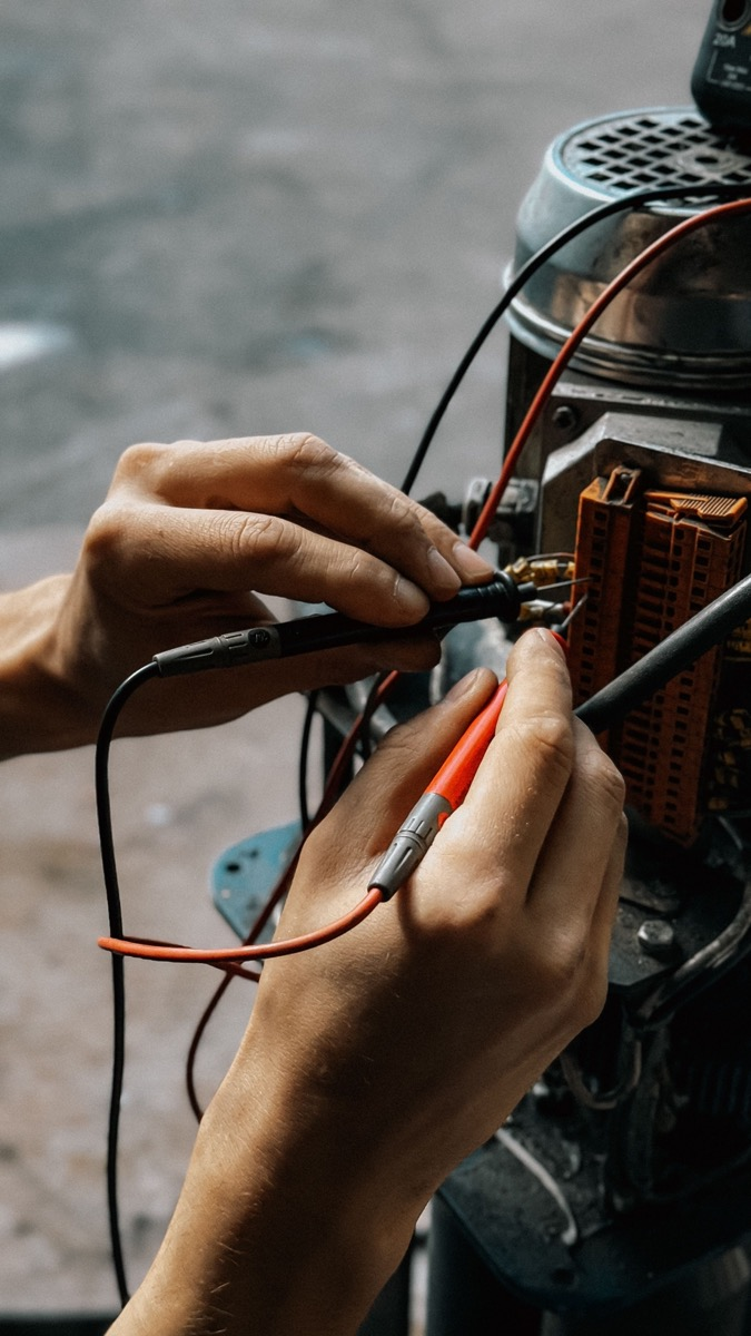
Earth continuity and potential. Measure resistance and potential between the switch's earth and the drive frame's earth while the plant runs. A bonded network gives you low resistance and a small potential; a broken one gives you a shield carrying current it should not be carrying.
| Check | How to measure | Reasonable pass condition |
|---|---|---|
| FCS counters versus drive state | Before and after a controlled start, same port | Counters unchanged across the start |
| Powered device input during start | Measure at the device, not at the switch | Stays inside the device's specified input range |
| Earth continuity and potential | Resistance and voltage between switch earth and drive frame | Low resistance, small potential during running |
Surge and fast transient events deserve their own separate discussion, because a nearby lightning strike and a drive switching every few milliseconds are different phenomena requiring different protection. We cover the surge side elsewhere.
Once you have seen it once, VFD cable interference is among the easiest industrial faults to recognise, because the timing is so distinctive. The sequence that works is unglamorous: read the counters to confirm timing, give the motor cable a proper return path, then fix separation distance and bond the tray, then install a screened Ethernet cable terminated 360 degrees at both ends. Most sites find that the first two steps solve it and the rest was never necessary. Rayin's managed industrial Ethernet switches expose per-port error counters that make the first read possible, and the general immunity and emission expectations buyers typically reference for industrial locations are IEC 61000-6-2 for immunity and IEC 61000-6-4 for emission — those are acceptance criteria you set with your supplier, not claims we make about our own products.
How far should an Ethernet cable be from a VFD output cable?
Treat 150 mm as the floor: it is the clearance most widely quoted in industrial practice from the segregation sub-clause of IEC 61000-5-2, which covers keeping cable families apart. Where the two run parallel for tens of metres, use separate trays or a divider instead. Any unavoidable crossing should be at 90 degrees rather than at a shallow angle.
Do I still need shielded twisted pair if I already have good separation?
Not necessarily, and adding it without fixing the bonding usually disappoints. A screen only performs when it is terminated 360 degrees at both ends into a bonded path, so if there is no tray alongside the run, the money buys very little. Improve routing first, then decide whether screening still buys anything measurable.
Can I terminate the Ethernet shield at one end to avoid a ground loop?
Yes, but treat it as a compromise. Single-ended termination stops power-frequency current circulating in the shield where two structures sit on different earth potentials, which is a genuine problem, but it also gives up most high-frequency performance. Bond both ends once a proper common bonding network exists and revisit the decision then.
Will a better switch stop VFD interference entering my links?
Almost certainly not, because nothing in the coupling path is inside the switch. The noise reaches the cable through a shared return path or a long parallel run, and no amount of switching silicon changes either. What a managed switch does give you is per-port error counters, which tell you whether the drive is really responsible before you spend money.
Does running fibre solve the problem completely?
For the copper link it replaces, yes: there is no metallic path to couple into and no shield to terminate badly. It does not fix the power or earthing problems in the cabinet, and powered devices at the far end still need a clean supply. Fibre also converts the problem into one you can no longer measure using port counters.
Is 6 kV Surge Protection Necessary for an Industrial Ethernet Switch?
Why Industrial Switches Must Pass IEC 61000-4 Immunity Tests
How to Test Ethernet Cable From the Switch: TDR, DDM and CRC
Installation and routing guidance above comes from IEC TR 61000-5-2, Electromagnetic compatibility, Part 5: Installation and mitigation guidelines, Section 2: Earthing and cabling (Technical Report, edition 1.0, published 1997-11 by IEC TC 77), including its treatment of cable families, segregation distance, protective earthing conductors and common bonding networks. The generic industrial immunity and emission specifications referenced in the closing paragraph are IEC 61000-6-2 and IEC 61000-6-4 respectively, and they are named as acceptance criteria a buyer may specify, not as any claim about a Rayin product. The 2 to 16 kHz carrier figure, the 150 mm separation floor and every rule of thumb are industry-typical values, labelled as such, and nothing here is a measured figure from a Rayin product unless it says so. This article is written by Sara, who checked each source and each number before publication. It is not a certification claim for any product or installation.
About the author: Sara — Sara is a Customer Manager at Rayin with over 10 years of experience in the communications field. In her free time, she enjoys badminton and swimming.
About Rayin: Shenzhen Rayin Technology Co., Ltd. — Company Profile