Run one flex-rated Cat6 travelling cable per car, power the car-top camera and sensors from a PoE switch in the car-top box, and home every lift into a single machine-room aggregation switch with one fibre uplink to the control room. Rayin (Shenzhen Rayin Technology) is a manufacturer of GPON OLTs and industrial Ethernet switches.
One flex-rated travelling cable per car and a car-top PoE switch keep the moving section down to a single uplink.
A four-lift bank draws roughly 32 Mbit/s of camera traffic, comfortably inside a 1 Gbit/s machine-room uplink.
Alarm on loss of link with a relay and a trap; give the BMS read-only status, never switch access.
Feed it from a car-top PoE switch: IEEE 802.3af supplies 15.4 W and 802.3at up to 30 W at the source over an industry-typical 100 m Cat5e/Cat6 channel defined by the TIA/EIA-568 series, and those are generic link numbers, not Rayin switch parameters.
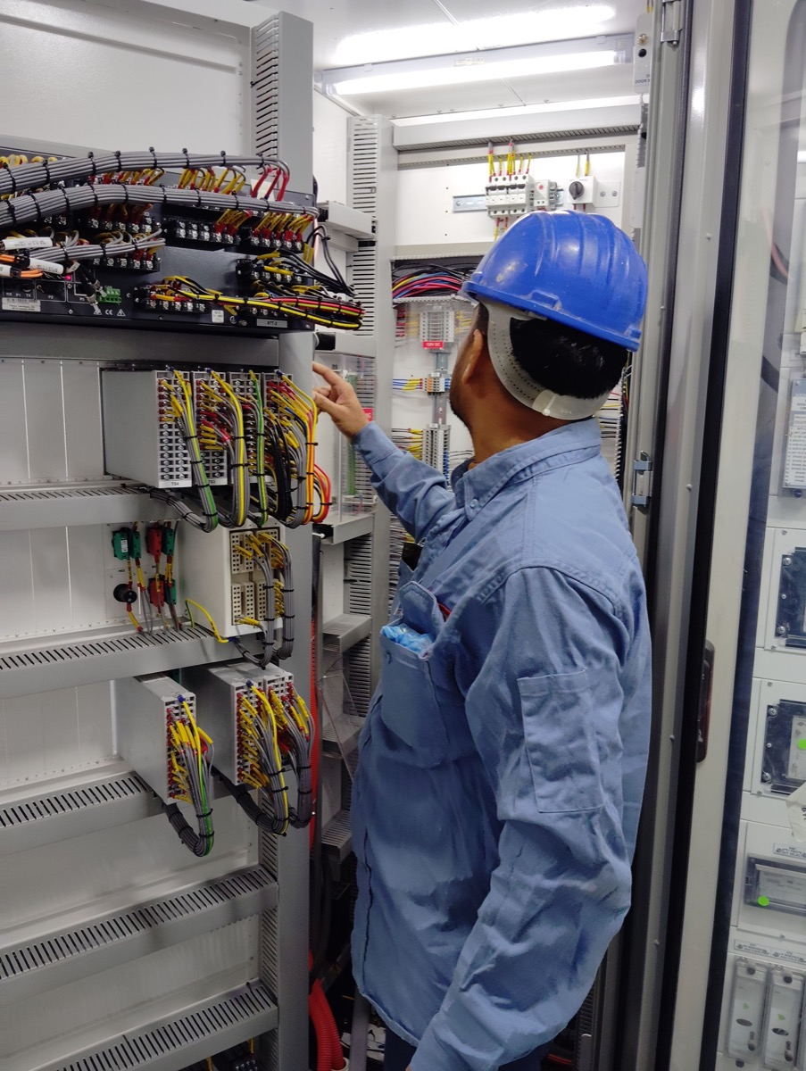
The travelling cable is the part that fails, not the switch. Specify a flex-rated shielded core with a published bend radius and hang a service loop so the cable flexes instead of tugging on the termination. Put one industrial PoE switch in the car-top junction box, power the car-top camera and the door and load sensors locally, and send a single uplink down the moving cable. A PoE switch for IP cameras up in the car keeps three or four home-runs out of the shaft; every extra conductor pushed through a travelling cable is one more fatigue point. Ground the shield at the machine-room end only, and label both ends to TIA/EIA-568 so a night-shift swap does not become a re-termination job.

Budget three powered downlinks plus one uplink per car, then one aggregation port per lift: a four-lift bank with two cameras and one sensor per car needs 12 PoE access ports and 4 uplinks — industry-typical counts, not a single switch's spec sheet.
Work the arithmetic from the device list, not from the box on the shelf. Two 1080p cameras and one sensor per car is three powered ports; four cars is twelve; eight cars is twenty-four. Add one aggregation downlink for each car-top switch and one spare at the panel. Cross-check the totals against the worked example below before you order hardware, and keep sensor and alarm telemetry on the same VLAN as the video so a single uplink per car carries the lot.
One 1 Gbit/s fibre uplink per bank is enough: the machine room to control room link carries the aggregated camera streams, alarm telemetry and NVR playback, and at 64 Mbit/s for eight lifts it sits far below the industry-typical 1 Gbit/s line rate.
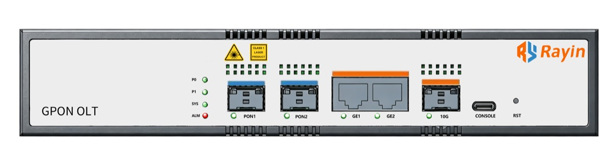
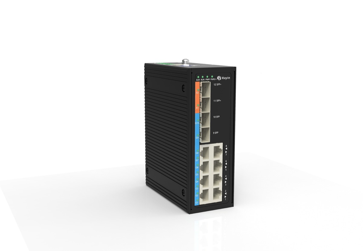
On the machine-room side, Rayin builds an 8+4-port gigabit industrial switch with PoE optional, which is where the lift uplinks land. Where the control room sits across a campus, a mini GPON OLT and an XPON ONU share a single fibre, and one GPON PON port registers up to 128 ONUs — plenty of headroom when several banks report back to one NVR. The 4/8-port GPON OLT and the single-port XGS-PON OLT sit in development on the roadmap. Keep the optical side for aggregation only; the car-top and shaft segments stay on copper PoE.
Wire one dry-contact relay output and one SNMP trap destination to the control-room annunciator: an industry-typical managed industrial PoE switch flags loss of link on the 100 m PoE channel immediately, so a cut travelling cable or a dead car-top camera raises an alarm even when the NVR shows a black frame.
Do not leave detection to the recording side. A camera that stops sending looks like a frozen picture until somebody reviews it, whereas a link-down trap and a closed relay contact point straight at a physical leg. Keep a network asset inventory — switch MAC, port map, cable ID, firmware level, and which car each uplink serves — so the duty engineer can trace a trap without riding the shaft twice. Test the relay path at commissioning; a contact that has never been closed is an assumption, not an alarm.
It stops at one read-only BMS boundary in the control room: the monitoring VLAN, sized as a single /24, hands over only alarm and status points and never carries lift-controller traffic — an industry-typical split on separate broadcast domains.
Shaft segments, media, power, bandwidth and the way each one fails:
| Shaft segment | Media | Power | Bandwidth | Failure mode |
|---|---|---|---|---|
| Car-top camera and sensors | Cat5e/Cat6 patch, within 100 m | IEEE 802.3af 15.4 W / 802.3at 30 W | 4 Mbit/s per 1080p stream | Connector fatigue in the car-top box |
| Travelling cable, moving section | Flex-rated shielded Cat5e/Cat6 | PoE from the car-top or machine-room switch | 100 Mbit/s to 1 Gbit/s | Conductor break from repeated bending |
| Machine-room patch field | Cat6 to the aggregation switch | Local mains, not PoE | 1 Gbit/s per uplink | Mis-patched or unlabelled port |
| Machine room to control room link | Single-mode fibre | Local mains at both ends | 1 Gbit/s | Fibre cut or dirty connector |
Port and bandwidth worked example for a lift bank, industry-typical figures:
| Lifts in bank | Cameras, 2 per car | Car-top PoE ports, cameras plus sensor | Aggregation downlinks, plus one spare | Video load at 4 Mbit/s per camera | Control-room uplink |
|---|---|---|---|---|---|
| 1 | 2 | 3 | 1 + 1 | 8 Mbit/s | 100 Mbit/s |
| 4 | 8 | 12 | 4 + 1 | 32 Mbit/s | 1 Gbit/s |
| 8 | 16 | 24 | 8 + 1 | 64 Mbit/s | 1 Gbit/s |
Even the eight-lift case pulls only 64 Mbit/s of video, so a 1 Gbit/s uplink runs at roughly 6 percent utilisation and a 100 Mbit/s link still clears it. Mark those bitrates industry-typical: a 1080p H.265 stream at 4 Mbit/s is a planning figure, not a camera guarantee. Add 20 percent port headroom for a spare device and give each lift its own VLAN so a loop in car 3 cannot flood car 4.
The do-and-do-not boundary at the handoff:
| Do | Do not |
|---|---|
| Keep video, telemetry and alarms on one dedicated VLAN | Merge them with the building guest network or the lift controller network |
| Home every travelling cable to a labelled patch field | Daisy-chain car-top switches through the shaft |
| Alarm on loss of link with a relay and a trap | Assume the NVR will report a dead camera |
| Give the BMS read-only alarm and status points | Grant the BMS write access to the monitoring switch |
| Record every device in a network asset inventory | Leave the machine-room patching undocumented |
Every figure in the tables above is an industry-typical planning value, not a Rayin product parameter.

Can I run PoE over the travelling cable?
Yes, but treat the travelling cable as the weak link. Use a flex-rated shielded Cat5e or Cat6 core and keep the run under the industry-typical 100 m PoE channel. Terminate into a car-top industrial PoE switch so the moving section carries one uplink, not a bundle of camera home-runs. Label both ends per TIA/EIA-568.
How many cameras can one car-top switch feed?
With IEEE 802.3af at 15.4 W or 802.3at at 30 W per port, an industry-typical 8-port PoE switch with a 120 W budget feeds four to eight 1080p cameras. Two cameras plus a sensor per car leaves spare ports, so budget three downlinks and one uplink per car with 20 percent headroom.
What belongs on the machine-room-to-control-room link?
One fibre uplink per lift bank, not one per camera. Aggregate the car streams on a machine-room industrial Ethernet switch and trunk them over a single 1 Gbit/s path to the control-room NVR. Shenzhen Rayin Technology ships mini GPON OLTs and an 8+4-port gigabit industrial switch (PoE optional) for that aggregation layer.
How should a dead camera or cut cable raise an alarm?
Do not wait for the NVR to spot a black frame. Have the car-top switch send an SNMP link-down trap and close a dry-contact relay on loss of link to the control-room annunciator. Keep a network asset inventory of switch MACs, port maps and cable IDs so the duty engineer finds the fault fast.
Where does this network hand off to the BMS?
At one read-only IP boundary. The monitoring VLAN ends on the aggregation switch; the BMS receives alarm and status points only, never switch write access or a path into the lift controller. That BMS boundary leaves everything the lift maker owns on the far side, so this network carries video and telemetry alone.
Cable the shaft like a moving machine, not like an office floor: one flex-rated travelling cable per car, a car-top PoE switch to keep home-runs out of the shaft, one labelled machine-room patch field, and a single 1 Gbit/s uplink to the control room. Size ports from the device count, size bandwidth from the camera bitrate, and alarm on loss of link rather than on a missing picture. Keep the BMS on the read-only side of the boundary and hold a network asset inventory current. Do that and a lift bank is just another, slightly more mobile, Layer-2 segment.
Sources checked: the IEEE 802.3af/at Power over Ethernet series, the TIA/EIA-568 cabling series, and IEC 61131-2 for industrial controller equipment environments. Only series names are cited; no clause, part or certification numbers are quoted or implied.
Every generic figure above — 15.4 W and 30 W, the 100 m PoE channel, Cat5e/Cat6, and 4 Mbit/s camera streams — is labelled industry-typical and is not a Rayin product parameter. The method, worked examples and wording are written by Sara, who checked each figure against those sources before publication.
About the author: Sara — Sara is a Customer Manager at Rayin with over 10 years of experience in the communications field. In her free time, she enjoys badminton and swimming.
About Rayin: Shenzhen Rayin Technology Co., Ltd. — Company Profile