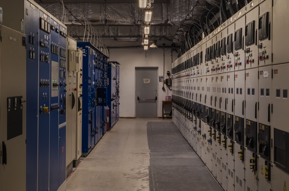
A camera network carries one-to-many video, and a Layer 2 switch has no way to learn which ports actually want that stream, so its default behaviour is to flood every frame to every port in the VLAN. IGMP Snooping stops the flood — but only while some device in the VLAN keeps querying the group table. That device is the IGMP Querier, and leaving it unassigned is the single most common reason a monitored network still stutters after Snooping is switched on.
Rayin (Shenzhen Rayin Technology) is a manufacturer of GPON OLTs and industrial Ethernet switches.
Below is the arithmetic behind both problems: how much bandwidth multicast flooding really eats, how the group table ages out, and how to size uplinks for a 120-camera site.
IPv4 multicast addresses live in 224.0.0.0/4, and they map to Layer 2 MAC addresses that always begin with 01:00:5E. The problem starts there: a Layer 2 switch forwards on its MAC address table, and a multicast MAC never appears as a source address, so the switch never learns which ports sit behind it. The default behaviour is therefore flood — copy the frame to every port in the VLAN except the one it arrived on.
That default is harmless in an office network with little multicast. A CCTV network is the opposite: video is the classic one-to-many flow. Put 32 cameras at 4 Mbps main stream in one VLAN and the total is 128 Mbps, all of which is flooded to every port. The access switch uplink carries it once; each camera port carries it again.
<Note> Two failure modes show up. A gigabit port survives 128 Mbps, but many PoE camera ports are Fast Ethernet — 128 Mbps is 1.28x line rate, so the port overloads and cameras drop and re-register, or the NVR loses the stream mid-recording. The other is accumulation: 200 cameras at 4 Mbps is 800 Mbps, 80% of a gigabit uplink, and once unicast and broadcast traffic stack on top there is no headroom left. </Note>
IGMP Snooping is blunt in the best way. The switch parses the IGMP messages that pass through it (version 1 in RFC 1112, version 2 in RFC 2236, version 3 in RFC 3376), records "which port asked for which group" in a multicast forwarding table, and from then on sends that group's frames only to the recorded ports. Every other port is spared.
Nothing changes on the host side. An NVR already has to send an IGMP Membership Report to receive multicast; Snooping merely writes that report down. The switch does not join the IGMP conversation — it is an observer, not a member, which is exactly why the feature is called Snooping and not Proxy.
The version differences decide whether the group table converges in time, so "supports IGMP" is not enough when you specify hardware:
| Version | Standard | Group model | What it means in the camera VLAN |
|---|---|---|---|
| IGMPv1 | RFC 1112 | Join only, no explicit leave | Groups expire by timeout; table ages slowly; not recommended today |
| IGMPv2 | RFC 2236 | Leave message supported, 260 s group timeout | Best compatibility; what most NVRs and cameras use by default |
| IGMPv3 | RFC 3376 | Source-specific subscribe (SSM) | Lets a receiver subscribe to one camera's group; the switch must support it too |
One detail is easy to miss: how unknown multicast is handled. Frames with no matching table entry can be flooded or dropped depending on the implementation, and RFC 4541 recommends dropping or rate-limiting them. On a camera VLAN, dropping unknown multicast blocks misconfiguration and scan traffic, at the cost of a few tens of milliseconds of packet loss while a new source comes up before its Report arrives — visible in the recording as a flicker on the first frame of each segment.
The multicast forwarding table is not static. It is kept alive by IGMP queries: the switch (or an upstream Layer 3 device) periodically sends a General Query, hosts answer with a Report, and the entry is refreshed. Using the RFC 2236 recommended values — 125 s query interval, 10 s maximum response time, robustness factor 2 — the group membership interval works out to:
2 x 125 + 10 = 260 seconds
So if nothing in the VLAN sends queries, every group entry is aged out at most 260 seconds after it was created. The NVR's next Report rebuilds it. The cycle repeats roughly every four and a half minutes, and for a window of tens of seconds to a minute inside each cycle the switch has no idea where that group should go — so it floods or drops. What the user sees is the picture freezing for a few seconds at regular intervals, or bandwidth utilisation oscillating on a pattern.
This is the most typical cause of "Snooping is on but it still stutters". The fix is to nominate one device in the VLAN as the Querier:
If the upstream is a Layer 3 device (a Layer 3 industrial switch, say) with multicast routing already enabled (PIM-SM or PIM-DM), let it be the Querier — that is the natural choice.
If the whole CCTV network is Layer 2, which is very common, pick one switch and turn on its Snooping Querier function so it takes the role.
When several candidates exist, the lowest source IP wins. Set the address of the intended Querier to the lowest value by hand rather than leaving the election to chance.
The scenario: 120 1080p cameras at 4 Mbps H.265 main stream; 6 NVRs, each subscribing to 20 channels; five 24-port gigabit PoE access switches, each uplinked to the core over one gigabit fibre port; the entire surveillance network in a single VLAN with no segmentation.
Step 1 — total multicast volume. 120 x 4 Mbps = 480 Mbps.
Step 2 — the cost of not running Snooping. Each access switch floods 480 Mbps to its 24 local ports, many of them Fast Ethernet PoE. 480 Mbps / 100 Mbps = 4.8x overload; traffic above line rate is dropped outright, showing up at the camera as packet loss and re-registration. The gigabit uplink has to carry 480 Mbps of multicast plus unicast, 48% utilisation, with no margin for peaks.
Step 3 — traffic with Snooping on. Multicast goes only to subscribed ports. Assume the six NVRs are spread evenly over three access switches, two per switch, 20 channels each: one access switch uplink carries 2 x 20 x 4 Mbps = 160 Mbps, 16% of the gigabit uplink. Camera ports subscribe to nothing and receive 0 Mbps of multicast, leaving their full port budget for their own 4 Mbps encode upload.
Step 4 — the core side. The three NVR-bearing access switches present 480 Mbps in total. On a 10G uplink that is 4.8%; on gigabit it is 48%, which means link aggregation or splitting the site into zones with separate VLANs.
Step 5 — the Querier time budget. With no Querier, the group timeout is 260 seconds, so an entry flickers roughly every 4.3 minutes. If multicast is dropped during that window, an NVR recording 20 channels at 4 Mbps loses all 20 at once for tens of seconds. Across an 8-hour shift that is about 111 flicker windows a day. That number is why the Querier is not optional.
The snippet below uses generic syntax to show the options and their order; it is not a real command line from any vendor.
; Step 1: enable IGMP Snooping globally and pin the version
  igmp-snooping enable
  igmp-snooping version 2

; Step 2: enable it inside the VLAN the cameras live in (per-VLAN)
  vlan 100
    igmp-snooping enable

; Step 3: on a pure Layer 2 network, designate the Querier
  vlan 100
    igmp-snooping querier enable

; Step 4: mark the uplink as a router port so reports go that way
  interface GigabitEthernet0/0/24
    igmp-snooping router-port

; Step 5: drop unknown multicast so unsubscribed groups cannot flood
  vlan 100
    igmp-snooping unknown-multicast discard
One ordering rule is hard: the Querier must be enabled inside the same VLAN, and no more than one Querier should be competing for election, or query messages duplicate and the group table oscillates. On a rollout of any size, pushing this as a template beats typing it into each switch.
| Symptom | Root cause | Fix |
|---|---|---|
| Picture breaks up for a few seconds every few minutes | No Querier in the VLAN; entries age out at 260 s | Enable Snooping Querier, or let an upstream Layer 3 device send queries |
| Worse after enabling Snooping | Multicast storm suppression applied to the ports carrying video | Do not rate-limit multicast; suppress only broadcast and unknown unicast |
| Live view unavailable across subnets | Layer 3 device has no multicast routing, or IGMP is not enabled on the interface | Enable PIM-SM on the Layer 3 device and IGMP on the interface |
| One NVR only shows part of its channels | Group address reused, or the NVR never sent a Report for that group | Check the NVR subscription list and the group address plan; one group should not be shared by several sources |
| Whole network slows after adding cameras | Uplink bandwidth too small and no aggregation | Recheck with step 4 above; move the uplink to 10G or aggregate |
| Cameras die together during a broadcast storm | Snooping handles multicast only; broadcast still floods | Configure broadcast storm suppression separately, with a threshold set from real traffic |
The third row is the most overlooked: IGMP Snooping works at Layer 2 only. When the core is a Layer 3 device and the NVRs sit on a different subnet from the cameras, Snooping alone does nothing — the Layer 3 device must run a multicast routing protocol (PIM-SM or PIM-DM) and IGMP on the interface facing the camera segment. Without that step, the request dies at Layer 3.
The second row is a counter-intuitive edge case: storm suppression exists to catch abnormal traffic, while video multicast is normal traffic. Setting a multicast suppression threshold on a port that carries video is a gate on a legitimate stream — once several channels stack above the threshold, packets drop and the picture breaks up on a regular pattern. Suppress broadcast and unknown unicast instead, and let the Snooping table govern multicast.
VLAN segmentation. Cameras and office terminals must sit in different VLANs. In one VLAN, office broadcast interferes with video and group table entries affect each other.
Querier assignment. On a pure Layer 2 network, designate one switch by hand; with a Layer 3 core, let the core do it.
Uplink bandwidth. Size it as "channels subscribed on this switch x bitrate" and keep 50% headroom.
Unknown multicast. Choose discard, so a misconfiguration cannot flood the whole network.
Storm suppression. Limit broadcast and unknown unicast only; do not rate-limit the multicast ports.
Cross-subnet multicast. Enable PIM on the Layer 3 device and IGMP on the interface — both sides.
Rayin's managed industrial PoE switch (8 gigabit ports plus 4 SFP uplinks) supports IGMP Snooping with Querier and per-port storm suppression, which is the combination a camera-and-NVR segment needs to isolate multicast; port and power figures are on the industrial switch solution page. Where the surveillance network spans sites, an OLT from the PON access solution can handle the uplink and replicates multicast on the PON side as well.
What is the difference between IGMP Snooping and IGMP Proxy? Snooping listens: the switch only reads the Reports hosts send, transmits no IGMP messages of its own, and depends on an external Querier to age the table. Proxy answers: the switch acts as the querier toward the hosts and as a host toward the upstream, so it can maintain the group table by itself. A CCTV network of a few dozen devices is fine with Snooping plus a manually assigned Querier; Proxy earns its keep at hundreds of groups with no Layer 3 device in the path.
Why is it worse after enabling Snooping? Two possibilities. Either a multicast storm suppression threshold was applied to the video ports, so normal streams are throttled as if they were abnormal; or the forwarding table is wrong — for instance the multicast source sits on a router port and is misclassified, so the stream is sent to a single port and other subscribers receive nothing. Diagnose in that order: check the port list against each group address in the multicast table first, then check whether any multicast rate limit is active on the ports.
How should multicast addresses be planned? One address per stream. Give 120 cameras 120 distinct group addresses rather than sharing one group across several streams, because a shared group forces every subscriber to receive the full volume and erases the isolation Snooping provides. Choose the range from 239.0.0.0/8 — administratively scoped multicast that will not be routed onto the public internet — and stay away from reserved blocks such as 224.0.0.0/24, which protocol control messages use.
Twenty-four cameras on a 24-port switch: is VLAN segmentation worth it? Yes, but one VLAN per switch is not required. Two or three by function is enough: cameras, NVRs and management. A camera's encode leaves as unicast to an NVR or as multicast distribution, and in both cases a smaller broadcast domain is steadier. The immediate payoff of a separate management VLAN is that device management traffic does not compete with video for bandwidth, so remote diagnosis is not disturbed by the stream.
Do camera ports need to be Fast Ethernet or gigabit? A single 1080p main stream at 4 Mbps fits a Fast Ethernet port. That port also carries the sub-stream used for mobile preview, ONVIF signalling and time synchronisation, but the total usually stays under 10 Mbps. Port speed is therefore not the bottleneck — what overloads the port is the full multicast stream flooded in before Snooping is enabled. That is also why camera ports that used to drop repeatedly become stable once Snooping is running.
OLT, PON and Uplink Isolation: Stop Network Loops and Broadcast Storms
What Is DHCP Snooping and How Switches Block Rogue DHCP Servers
Why SCADA Needs a Managed PoE Switch With No Single Point of Failure
About the author: Sara — Customer Manager at Shenzhen Rayin Technology Co., Ltd., 10+ years helping ISPs and integrators build industrial networks.
About Rayin: Shenzhen Rayin Technology Co., Ltd. — Company Profile