Configure the Vlanif gateway and the addressing first, and the static routing vs dynamic routing question answers itself: every subnet on one device needs nothing but connected routes, while more than five remote subnets or a redundant path calls for OSPF plus BFD. A Layer 2 switch forwards on its MAC address table, and once broadcast domains are separated by VLANs the VLANs cannot see each other at Layer 2 at all. Getting a PLC in VLAN 10 to reach a server in VLAN 20 takes a device in the middle that can read both IP and MAC — that job is the Layer 3 switch.
Rayin (Shenzhen Rayin Technology) is a manufacturer of GPON OLTs and industrial Ethernet switches.
The Layer 3 switch builds one logical interface per VLAN, commonly named Vlanif and called an SVI (Switch Virtual Interface) in the other naming system. That interface holds an IP address, holds a MAC address, and takes part in ARP, so to a host it is an ordinary gateway. Once the IP is assigned, the connected route for that subnet enters the routing table on its own — nothing to write by hand.
The boundary between Layer 2 and Layer 3 sits at the IEEE 802.1Q tag. Frames carrying a VLAN tag are switched internally by the MAC table; once they reach the gateway, the next-hop lookup consults the IP routing table. Traffic inside one subnet never leaves Layer 2, and only cross-subnet traffic triggers Layer 3 forwarding. That decides where the gateway belongs: put it at the access layer and cross-subnet traffic climbs to the core and comes back down; put it at the core and the path is the shortest available.

Step one: create the VLANs. The 802.1Q VLAN ID is 12 bits, usable range 1–4094. The usual industrial practice is to divide by function — one VLAN each for the control network, the monitoring network, the office network and device management — and never by physical location. Devices get moved; functions do not.
Step two: build the Vlanif and assign its IP. One subnet per VLAN, with the gateway address conventionally the first usable address in that subnet, for example 192.168.10.1/24. Hosts point at it as their gateway, and only then do cross-subnet requests get handed to the Layer 3 device.
Step three: read the routing table. If every subnet in the network hangs off this one Layer 3 switch, the Vlanif interfaces alone are enough — the table holds nothing but connected (Direct) entries, with no static routes and no protocol. This is the step most often over-engineered: a dozen access switches and a dozen VLANs on a single core box, and forcing an OSPF configuration on top only adds a set of things that can be misconfigured.
Only when more than one Layer 3 device exists does anything need to exchange routes between them.
| Dimension | Static routing | Dynamic routing (OSPF) |
|---|---|---|
| Configuration effort | One entry per remote subnet; a new subnet means touching every device | Announce the subnet once, propagation is automatic |
| Failover | No automatic switchover; needs a floating static route or liveness probing | Relies on neighbour timeout, 40 s dead interval by default, tunable |
| Convergence time | Manual intervention, minutes | 40 s by default; about 12 s with hello 3 s / dead 12 s; 150 ms with BFD |
| Resource cost | Practically zero | Neighbour packets and SPF calculation consume CPU, more visible as the table grows |
| Troubleshooting | The routing table reads at a glance | Requires neighbour state, LSAs and area design |
| Suitable scale | Three to five subnets, topology barely changes | A dozen or more subnets, redundant links present |
The decision comes down to a single line: beyond five remote subnets, or with more than two reachable paths, run OSPF — otherwise stay static. The classic industrial shape of a headquarters plus three workshops is fully served by static routes plus a primary and a backup default route; an OSPF configuration there would drag in area design and DR election for no gain.
Convergence time is what actually hurts. On a broadcast network OSPF defaults to a 10-second Hello and a 40-second Dead interval, so a broken link is not declared dead for 40 seconds — and 40 seconds of lost communication on a production line is a stoppage. Three ways to compress it:
Move Hello/Dead to 3 s / 12 s, which brings convergence to roughly 12 s — still the wrong order of magnitude for a production line.
Add BFD (RFC 5880). A 50 ms detection interval multiplied by three failures triggers switchover in about 150 ms, at the cost of both ends supporting it and having CPU headroom.
Leave the redundancy at Layer 2 with a ring protection protocol — RSTP converges in about a second under IEEE 802.1D-2004, and MRP reaches the 200 ms class under IEC 62439-2 — and let Layer 3 do nothing but path selection.
The combination seen most often in real projects is the third plus the second: the ring handles link-level fast recovery, and OSPF with BFD handles fast switchover between subnets.
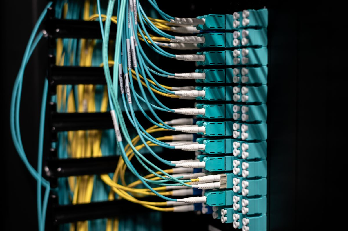
The scenario: a campus with 8 VLANs, one /24 each; one core Layer 3 industrial switch with 8 gigabit ports plus 4 SFP ports, carrying 6 Layer 2 access switches underneath; and a second Layer 3 switch across the plant, connected to the core by a fibre pair, holding 4 subnets of its own.
Step 1 — total address space. Each /24 offers 254 usable host addresses. 8 local VLANs × 254 = 2,032; the cross-plant switch adds 4 × 254 = 1,016. Total 3,048 usable addresses. With the 30% headroom common in industrial planning, the actual device count should stay under about 2,345.
Step 2 — route entries. The 8 local VLANs configured as Vlanif produce 8 connected routes. Reaching the 4 remote subnets needs 4 more entries: as static routes that is 4 lines; under OSPF the same 4 subnets are announced and the protocol generates them. At this scale the two routing tables look nearly identical, around 12 entries, and the difference only appears the next time a subnet is added.
Step 3 — forwarding capability at each layer. A gigabit port at 64-byte minimum frames forwards at 1000 Mbps ÷ (64 + 20) bytes × 8 = 1.488 Mpps. A Layer 3 switch performs route lookup in an ASIC and holds that 1.488 Mpps per port at line rate; a router forwarding in software on the same traffic typically manages a few hundred kpps — three orders of magnitude apart. That gap is why intra-campus inter-VLAN routing belongs on a Layer 3 switch rather than a router.
Step 4 — convergence. With OSPF left at its defaults, a break on the cross-plant fibre leaves the core waiting out the 40-second Dead interval. At a line producing 20 units a minute with a gross margin of 5 yuan per unit, 40 seconds costs about 13 units, or 65 yuan — trivial on its own, but if the broken link carries the control network of the whole line the real cost becomes downtime hours and scrapped product, a different order of magnitude entirely. Adding BFD at 50 ms × 3 between the core and the cross-plant switch cuts the switchover to 150 ms, which the production side essentially cannot feel.
Step 5 — jitter from ARP and MAC aging. A Layer 3 switch ages its ARP table every 20 minutes and its MAC table every 300 seconds by default. At the instant of a switchover, if the destination MAC has already aged out, the device has to flood ARP again, which adds tens of milliseconds and a burst of broadcast traffic. On sites where the redundant path switches over often, lengthening ARP aging on critical subnets to 5–10 minutes runs more steadily; the price is that an IP conflict takes longer to surface.
The snippet below is generic syntax showing the sequence and where each parameter sits. It is not a real command line from any vendor.
; Step 1: create the VLANs
; Step 2: assign ports to VLANs (uplinks run as trunk, permitting several VLANs)
; Step 3: build the Vlanif and assign the gateway address (connected routes generate themselves)
; Step 4a: static routes pointing at the cross-plant subnets
; Step 4b: or switch to OSPF and announce the local subnets
; Step 5: add BFD on the cross-plant link to pull convergence down to 150 ms
min-tx-interval 50 min-rx-interval 50 detect-multiplier 3
Two ordering rules cause a large share of field faults. A Vlanif can only take an IP address after its VLAN exists; and if a trunk port does not permit a given VLAN, the Vlanif built on that switch stays down no matter how complete the configuration looks.
A Layer 3 industrial switch routing inside a campus is the right tool, but four boundaries have to be respected.
A single gateway is a single point of failure. When every subnet's gateway lives on one device, that device failing takes the whole network down. Redundancy means VRRP (RFC 5798): two devices share a virtual IP and switchover typically takes 1–3 seconds; stricter control networks use dual network interfaces on the device side with a redundancy protocol.
Finer subnetting is not automatically better. Eight /24s is a comfortable size. Splitting into 32 /26s shrinks the broadcast domains but doubles the route entries, the ARP table and the DHCP scopes, and management cost grows faster than the benefit.
Layer 3 ACL and table capacity have ceilings. An industrial switch carries a far smaller routing table and ACL entry count than data-centre hardware. Past a few hundred entries, read the datasheet instead of assuming it fits.
Broadcast and loops remain a risk above Layer 3. Layer 3 separates broadcast domains; it does nothing about a loop inside a VLAN. Port isolation, storm suppression and spanning tree all need to be in place, or one mispatched cable can saturate the core.
| Symptom | Likely cause | Action |
|---|---|---|
| Same VLAN works, cross-VLAN fails | Host gateway wrong, or the Vlanif has no IP | Check gateway and ARP on the host; verify the Vlanif state |
| Some subnets reachable, others not | Trunk port does not permit that VLAN | Check the permitted VLAN list on both ends of the link |
| Recovery takes 40 seconds after a link break | OSPF Dead interval left at default, no BFD | Tune hello/dead or enable BFD |
| Brief packet loss after a switchover | Aged ARP and MAC entries must be relearned | Shorten aging or add static ARP binding |
| Core CPU saturation | Too many route entries driving frequent SPF runs, or a loop | Review neighbour flapping logs and consolidate routes |
| Touching one access switch means touching the core | Static routes with subnets added frequently | Move to OSPF, or consolidate subnets onto the core |
Every subnet on one Layer 3 device → configure Vlanif only, add no protocol.
Five or fewer remote subnets and a fixed topology → static routes plus a backup floating static route.
More than five remote subnets, or multiple paths → OSPF, with BFD configured alongside it.
Switchover required in under a second → keep the redundancy at Layer 2 (RSTP or MRP) and let Layer 3 only select the path.
The gateway must never interrupt → two devices running VRRP, or device-level redundancy.
Unsure how many layers you need → get the VLAN and address plan right first; the protocol choice matters far less than a wrong addressing plan.
Rayin's industrial switch line includes an 8-port gigabit model with 4 SFP uplinks that supports Layer 3 static routing and OSPF; the industrial switch solution page lists port counts and Layer 3 capability, and where the campus also runs PON access, the OLT uplink can land directly on this switch's optical ports as described on the PON access solution page.
Can a Layer 3 switch fully replace a router? Inside a campus, for inter-VLAN routing, yes — a model such as Rayin's 8-port gigabit switch with 4 SFP uplinks, which supports Layer 3 static routing and OSPF, carries that role. Across a WAN egress, no. A Layer 3 switch is strong at ASIC line-rate forwarding and low-cost high port density, but NAT, VPN, policy routing and traffic shaping are usually weak or absent. The standard layout is a Layer 3 switch handling the campus core and inter-VLAN routing, with a router at the egress for NAT and leased-line termination — a division of labour, not a replacement.
What happens when a Vlanif's IP goes down? The Vlanif address is logical: as long as any physical port in that VLAN is up, the Vlanif is up. When every physical port in the VLAN goes down, the Vlanif goes down too, the connected route leaves the routing table, and that subnet becomes unreachable immediately. So whether a Vlanif is usable cannot be judged from the configuration alone — check whether it has any live physical port underneath.
Why is there no OSPF neighbour even though the configuration looks right? Three causes cover most cases. The interface was not announced into the area (the network statement's subnet or wildcard mask is wrong). The two ends have conflicting router IDs. Or the interface was set to silent mode. For troubleshooting, look first at whether the neighbour state sits in Init or ExStart: stuck in Init usually means one-way reachability, stuck in ExStart usually means an MTU or router-ID mismatch.
With 8 /24s, is address space being wasted? No. Each /24 gives 254 usable addresses, 2,032 across 8 VLANs. A workshop carrying 30–60 devices is normal on an industrial floor, so one /24 per workshop's control equipment is comfortable and leaves room to grow. What does waste space is giving a /24 to a VLAN holding only a handful of devices — in that case merge VLANs by floor or production line and bring the count down to 4–6.
Can static routing and OSPF run together? Yes, and it is common. The stable local subnets stay connected, fixed subnets across a WAN or a third party stay static, and the backbone that needs automatic failover runs OSPF; a route import then injects the static routes into OSPF. Tag the imported routes or filter them, otherwise the two sides importing each other's routes will produce a suboptimal path.
Network Segmentation Plan: VLANs and IP Subnets for Campus Networks
OSPF Routing Protocol Application Guide for Large Industrial Networks
About the author: Sara — Customer Manager at Shenzhen Rayin Technology Co., Ltd., 10+ years helping ISPs and integrators build industrial networks.
About Rayin: Shenzhen Rayin Technology Co., Ltd. — Company Profile